Rockwell Automation AADvance Controller System Build User Manual
Page 99
Document: 553632
(ICSTT-RM448_EN_P) Issue: 08:
4-19
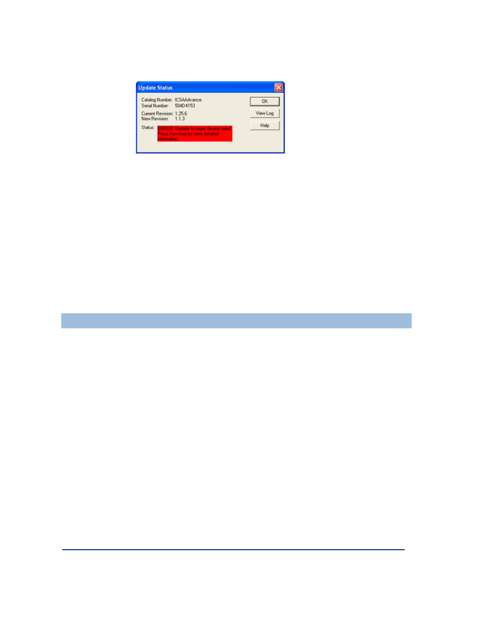
10)
Click OK and another error message is displayed.
11)
Click OK then Cancel to Exit ControlFLASH.
12)
Reboot the processor module by switching the power OFF then ON and hold in
the Fault Reset button as the module reboots until the Aux LED goes amber.
The processor module(s) will reboot into the Recovery Mode indicated by the
following LED states on the processor module.
Healthy
Green (dependent on Module health)
Ready
Amber
Run
Amber
System Health
Green (dependent on system health)
Force
Amber
Aux
Amber
Stage 2: Installing the ControlFLASH Firmware Kit for OS, FPGA, LSP and BUSP
Stage 2: Installing the ControlFLASH Firmware Kit for OS, FPGA, LSP and BUSP
Stage 2: Installing the ControlFLASH Firmware Kit for OS, FPGA, LSP and BUSP
Stage 2: Installing the ControlFLASH Firmware Kit for OS, FPGA, LSP and BUSP
This procedure describes how to upgrade the Processor Firmware for OS, FPGA, LSP
and BUSP.
The procedure that follows is basically the same as for stage 1.
1)
Run the 354400_102_ControlFLASH.msi file.
2)
Click NEXT.
3)
Read and agree the License.
4)
Click Browse to select the location of the installation or Next to choose the
default location.
5)
Click Next to confirm the installation.
ControlFLASH installs and shows the progress bar.
6)
Click Yes I want to launch ControlFLASH, then click Close.