Step 2: removing the old power structures, Removing the protective screens and covers – Rockwell Automation 20D PowerFlex 700H/S Frame 14 Replacement Power Structures User Manual
Page 3
PowerFlex® 700S and 700H Frame 14 Replacement Power Structures
3
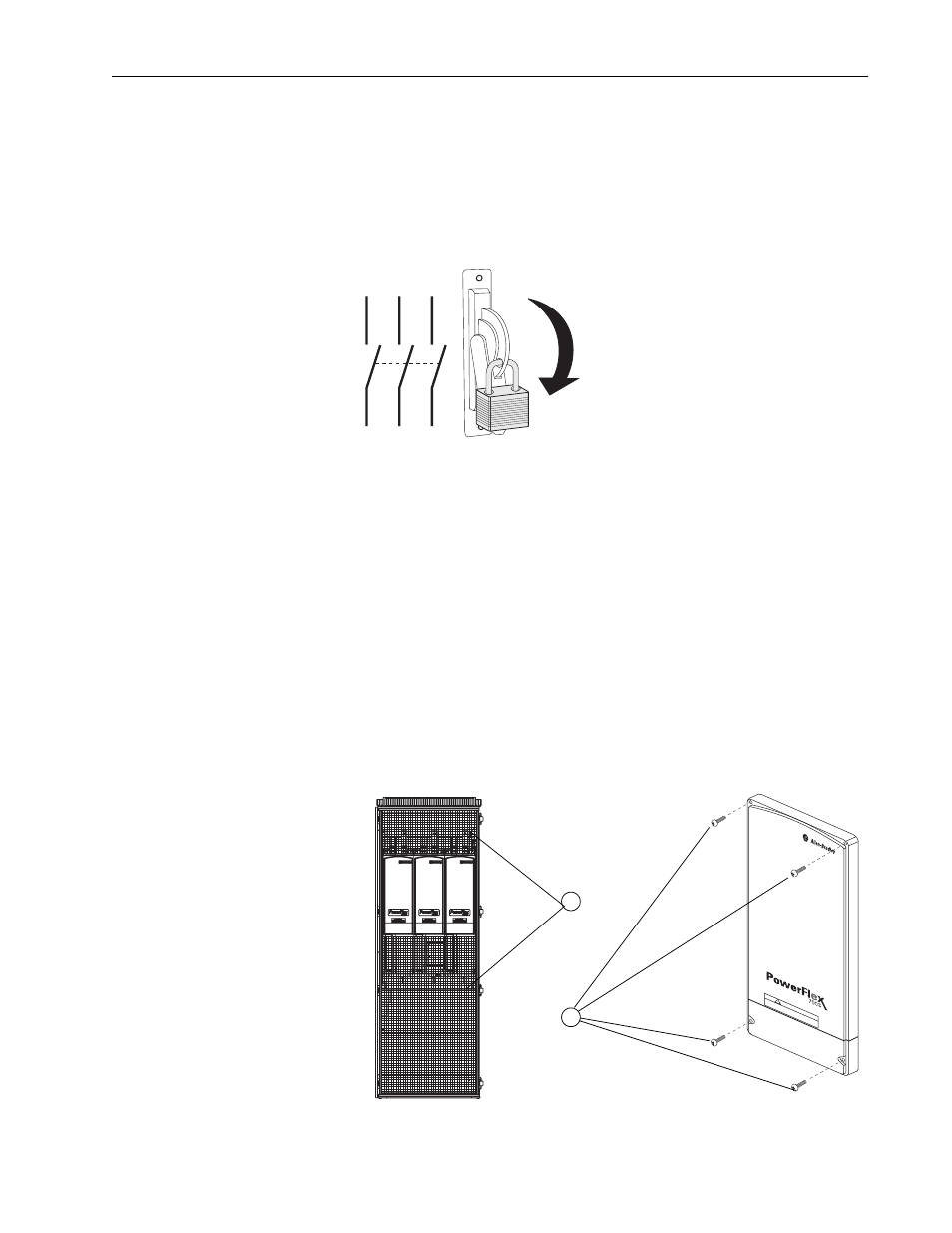
1. Turn off and lock out input power. Wait five minutes.
2. Verify that there is no voltage at the drive’s input power terminals.
3. Measure between the +DC and -DC terminals, between the +DC
terminal and the chassis, and between the -DC terminal and the chassis.
The voltage must be zero for all three measurements.
Step 2: Removing the Old
Power Structures
Before you can remove the old power structures from the drive, you must
remove the protective screens, protective covers and air flow plates from the
drive.
Note: The following steps must be completed for both power structures in
the drive.
Removing the Protective Screens and Covers
1. For NEMA/UL Type 1 enclosures, remove the screws that secure the
protective screens to the enclosures and remove the screens.
2. Remove the four M5 POZIDRIV screws that secures each of the three
pairs of protective covers to the drive power structures and remove the
protective covers.
L1
L2
L3
O
I
DC B
US CONDUCT
ORS AND CAP
ACIT
ORS
OPERA
TE A
T HIGH
VO
LTA
GE.
REMO
VE PO
WER
AND W
AIT 5 MINUTES BEFORE SER
VICING
DA
NGER
!
1
Three covers
2