Step 3: installing the new power structures – Rockwell Automation 20D PowerFlex 700H/S Frame 14 Replacement Power Structures User Manual
Page 12
12
PowerFlex® 700S and 700H Frame 14 Replacement Power Structures
Step 3: Installing the New
Power Structures
Install the new power structures in reverse order of removal. Refer to the
publication PFLEX-IN006…, Installation Instructions - PowerFlex 700S
and 700H Drives Frames 9 - 14, for tightening torques of power and motor
terminations.
Step 4: Connecting the
Power Structures to
Components in the Drive
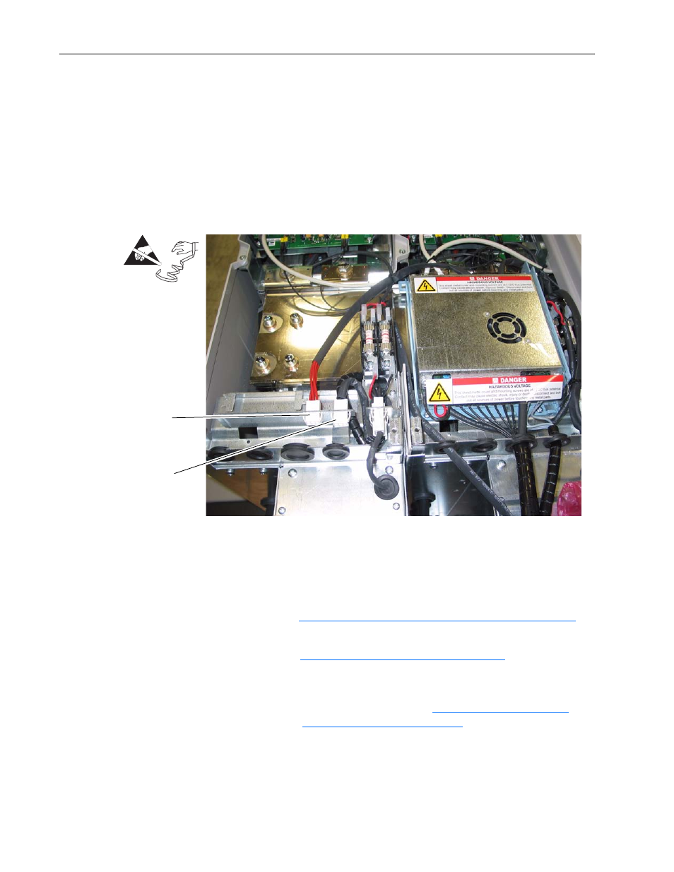
1. For drives with AC input, connect the precharge cable and remove the
jumper from the fan control connector and connect the fan control cable
from the Rectifying modules to the Power Structure.
2. Use the tables and illustrations below to make all connections between
the ASIC, ASIC Feedback, Common Mode Filter, Power Supply
Voltage Feedback and Fiber Optic Star Interface (700S) or Star Coupler
(700H) circuit boards for your installation.
– Refer to
PowerFlex 700S Phase II Drives Connections: on page 16
a PowerFlex 700S Phase II circuit board connection diagram.
– Refer to
PowerFlex 700H Connections: on page 19
for a PowerFlex
700H circuit board connection diagram.
Important: If the drive has DC input, you must also connect the
precharge circuit. Refer to
Drives with DC Input on page 21
.
=
Connect fan control
cables
Connect Precharge
cables