Connector data – Rockwell Automation TLY-Series Servo Motor User Manual
Page 19
TL-Series Servo Motors 19
Publication TL-IN003A-EN-P — June 2007
Connector Data
These tables provide signal descriptions for servo motors with TLY catalog numbers.
Absolute Encoder
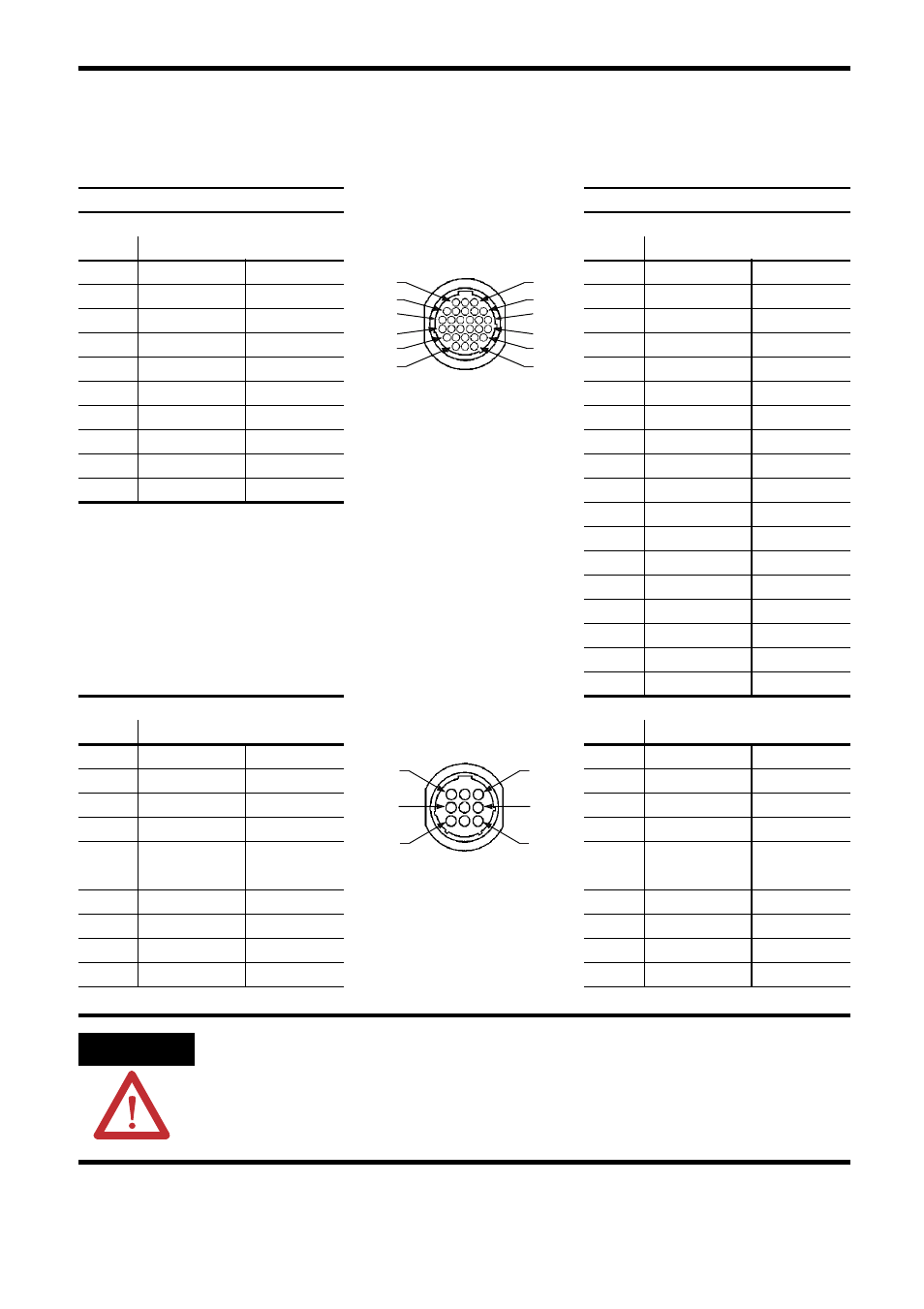
Connector Pinouts
Incremental Encoder
Feedback Connections
Feedback Connector
Feedback Connections
Pin
Signal
Tyco AMP 206152-1
Pin
Signal
1…5 Reserved
—
1…8 Reserved
—
6 BAT+
Brown
9 AM+
Green
7…12 Reserved
—
10
AM-
Green/blk
13 DATA+
Blue
11 BM+
Blue
14 DATA-
Blue/black
12 BM-
Blue/blk
15…21 Reserved
—
13
IM+
Yellow
22 EPWR
5V Red
14 IM-
Yellow/blk
23
ECOM & BAT- Black
15
S1+
Grey/blk
24
SHIELD
Drain wire
16
S1-
Grey
25…28 Reserved
—
17 S2+
Brown/blk
18 S2-
Brown
19 S3+
White/blk
20 S3-
White
21 Reserved
—
22 EPWR
5V Red
23 ECOM
Black
24 SHIELD Drain
wire
25…28 Reserved
—
Power and Brake Connections
Power and Brake Connector
Power and Brake Connections
Pin
Signal
Tyco AMP 206705-2
Pin
Signal
1
U phase
Red
1
U phase
Red
2
V
phase White
2
V
phase Black
3
W
phase Black
3
W
phase White
4
Reserved
—
4
Reserved
—
5 Ground Yellow/grn
&
drain wires
5 Ground Yellow/grn
&
drain wires
6 Reserved
—
6 Reserved
—
7 MBRK+
Yellow
7 MBRK+
Yellow
8 Reserved
—
8 Reserved
—
9 MBRK- Blue
9 MBRK- Blue
ATTENTION
Be sure that cables are installed and restrained to prevent uneven tension or flexing at
the cable connectors. Excessive and uneven force at the cable connector may result in
damage to the housing and contacts as the cable flexes. Failure to observe these safety
procedures could result in damage to the motor and its components.
3
14
8
20
28
25
1
9
4
15
26
21
3
6
9
1
4
7