Install the controlnet adapter, 8 xm controlnet adapter publication, Ms cha chb bps a b – Rockwell Automation 1440-ACNR XM ControlNet Adapter User Manual
Page 8
8 XM ControlNet Adapter
Publication
ICM-IN001A-EN-P - March 2009
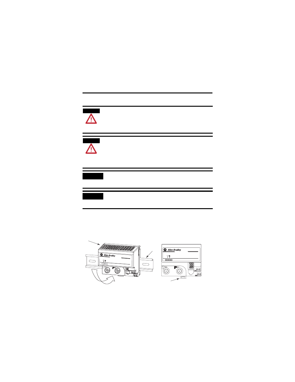
Install the ControlNet Adapter
To install the adapter on the DIN rail prior to installing the XM terminal base
units, follow these steps.
1. Position the ControlNet adapter module (A) on a 35 x 7.5 mm DIN
rail (B) at a slight angle.
ATTENTION
If you insert or remove the module while backplane power is on, an electrical
arc can occur. This could cause an explosion in hazardous location
installations.
Be sure that power is removed or the area is nonhazardous before proceeding.
ATTENTION
This product is grounded through the DIN rail to chassis ground. Use zinc
plated yellow-chromate steel DIN rail to assure proper grounding. The use of
other DIN rail materials (for example, aluminum or plastic) that can corrode,
oxidize, or are poor conductors, can result in improper or intermittent
grounding. Secure DIN rail to mounting surface approximately every 200 mm
(7.8 in.) and use end-anchors appropriately.
IMPORTANT
The 1440-DYN02-01RJ Dynamic Measurement module is used with the
1440-ACNR. Any other XM catalog number will not work with the
1440-ACNR.
IMPORTANT
The XM Bus must be terminated on each end with a 120 ohm, 1%, 1/4 W
resistor. Because the adapter has an internal terminator resistor, it should
be installed at one end of the XM Bus.
Cont rolNet XM A
dapter
1440-ACNR
XM
®
MS
CHA
CHB
BPS
A
B
Cont r olNet XM Adapter
1440-ACNR
XM
®
MS
CHA
CHB
BPS
C
31769-M