Rockwell Automation TLAR Electric Cylinders Replacement User Manual
Page 7
MP-Series and TL-Series Electric Cylinders Replacement Parts 7
Rockwell Automation Publication MPAR-IN002B-EN-P - September 2012
8.
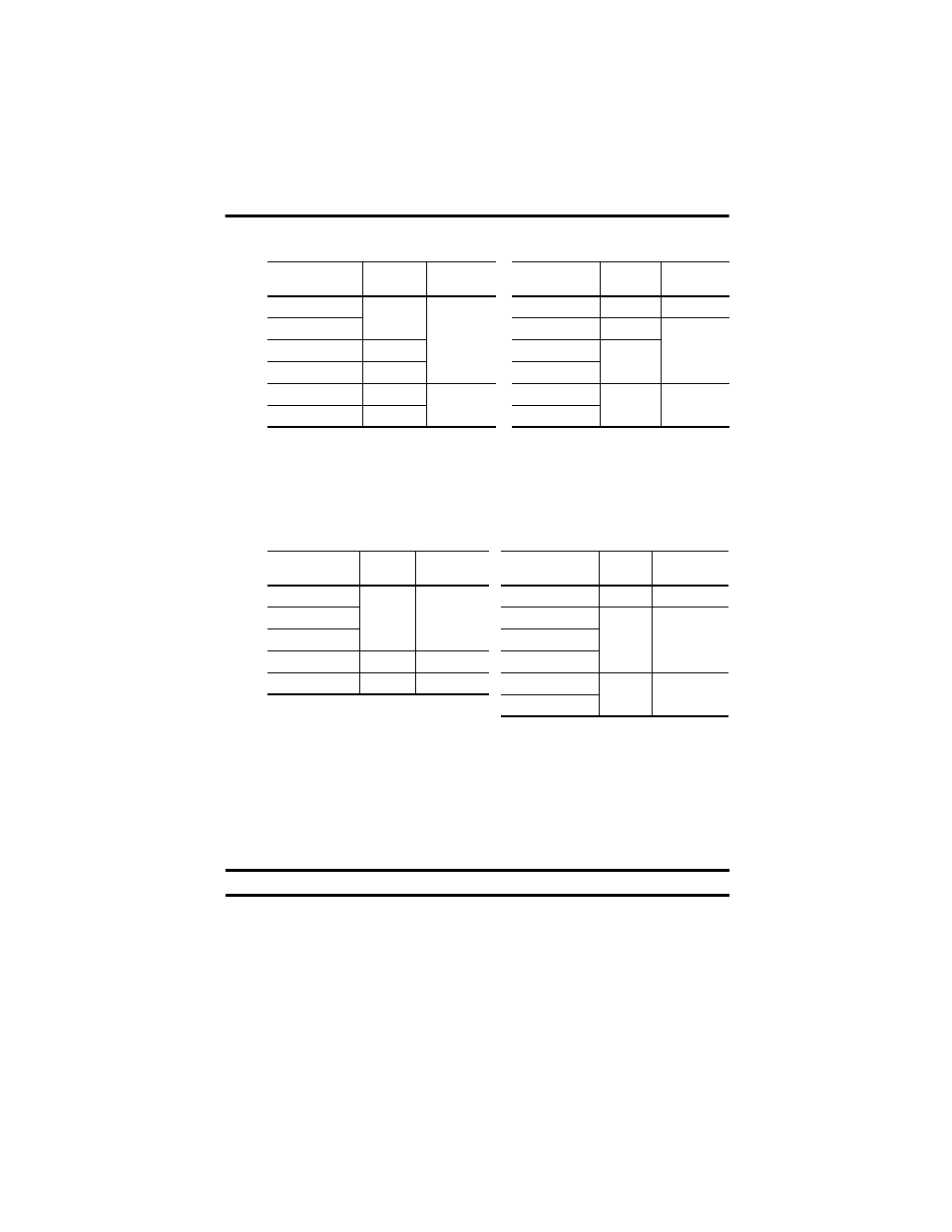
Align the coupling, the motor, and the actuator cylinder, then push them together.
9.
Attach the motor to the motor mount flange by using all four bolts.
10.
Torque the bolts as follows.
Replace Inline-mount Electric Cylinder Coupling or Actuator Cylinder
This procedure applies to Bulletin MPAR-
xxxxxx-xxA and TLAR-xxxxxx-xxA electric
cylinders.
Follow these steps to replace the coupling or actuator cylinder.
1.
Disconnect the motor and feedback cables.
Cat. No.
X
1
(1)
mm (in.)
(1)
Tolerance is ± 0.25 mm (0.010 in.).
Torque
N•m (lb•in)
Cat. No.
X
1
(1)
mm (in.)
Torque
N•m (lb•in)
MPAR-x1xxxB-xxA
18.5 (0.73)
4.0 (35.4)
TLAR-A1xxxB-BxA
25.0 (0.98)
0.6 (5.31)
MPAR-x1xxxE-xxA
TLAR-A1xxxE-BxA
28.8 (1.13)
4.0 (35.4)
MPAR-x2xxxC-xxA
19.5 (0.77)
TLAR-A2xxxC-BxA
29.8 (1.17)
MPAR-x2xxxF-xxA
22.3 (0.88)
TLAR-A2xxxF-BxA
MPAR-x3xxxE-xxA
35.5 (1.40)
8.0 (70.8)
TLAR-A3xxxE-BxA
30.5 (1.20)
8.0 (70.8)
MPAR-x3xxxH-xxA
35.2 (1.38)
TLAR-A3xxxH-BxA
Cat. No.
Bolt Size
Torque
N•m (lb•in)
Cat. No.
Bolt Size
Torque
N•m (lb•in)
MPAR-x1xxxx-xxA
M5 x 20
5.9 (52.2)
TLAR-A1xxxB-BxA
M4 x16
2.9 (25.6)
MPAR-x2xxxC-xxA
TLAR-A1xxxE-BxA
M5 x16
5.9 (52.2)
MPAR-x2xxxF-xxA
TLAR-A2xxxC-BxA
MPAR-x3xxxE-xxA
M6 x 25
9.9 (87.6)
TLAR-A2xxxF-BxA
MPAR-x3xxxH-xxA
M8 x 25
24.0 (212.4)
TLAR-A3xxxE-BxA
M6 x 20
9.9 (87.6)
TLAR-A3xxxH-BxA
IMPORTANT
Apply Loctite 222 to bolts
M4 and Loctite 242 for bolts M5 during assembly steps.