Functional ground screw – Rockwell Automation 6181F_P Series E Integrated Display Computers Installation Instructions User Manual
Page 19
Industrial Integrated Display Computers 19
Rockwell Automation Publication 6181P-IN010F-EN-P - July 2013
The power supply is internally protected against reverse polarity.
Follow these steps to connect the computer to a DC power source.
1. Verify the main power switch or breaker is off.
2. Verify that the DC power wires meet these requirements:
•
Material: Stranded copper
•
Wire gauge: 0.325…0.823 mm
2
(22…18 AWG)
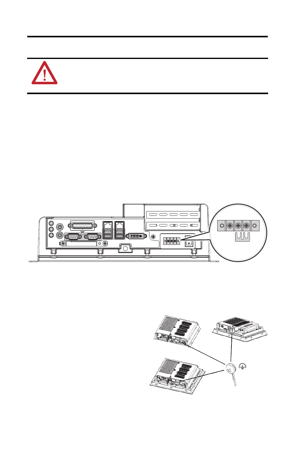
3. Secure the DC power wires to the terminal block screws, and the ground wire to the
GND terminal screw.
Tighten the terminal to a torque of 0.687 N•m (6.1 lb•in).
4. Apply 18…32V DC power to the computer.
Functional Ground Screw
The pre-installed functional ground screw is
not required for safety or regulatory
compliance. However, if a supplemental
ground is desired, use the functional ground
screw in the I/O port panel of the computer.
If using the functional ground screw, connect
the computer to earth ground by using
a 1.5 mm (16 AWG) or larger external wire.
Use a ground wire with green insulation and a
yellow stripe for easy identification.
ATTENTION: Use a SELV isolated and ungrounded power supply as input power to the computer.
This power source provides protection so that under normal and single fault conditions, the
voltage between the conductors and functional earth/protective earth does not exceed a safe
value.
Non-display Computer Shown
Pre-installed DC
Ground Bus Strip
+v -v
GND
Standard Computer
Non-display Computer
Performance Computer