Rockwell Automation 61C23 AutoMate Local I/O Head User Manual
Page 12
3Ć2
Step 5.
Connect the Local I/O Interface cable between the Local
I/O Head connector labeled INPUT and any Rail connector
on the hardware with which the Head will communicate.
Note that you can substitute the I/O Rail cable (M/N 45C5)
for the Local I/O Interface cable (M/N 45C8) in step 5
above. You cannot, however, substitute the Local I/O
Interface cable for the I/O Rail cable. If you do so, the Rail
will not operate.
Step 6.
Verify that power was disconnected from the wires that will
be used to provide power to the Head.
Step 7.
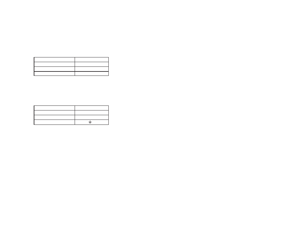
For M/N 61C22, connect 120 VAC and ground wiring to
the terminals on the Head faceplate as follows:
Input
Terminal Label
120 VAC hot
L1
120 VAC neutral
L2
ăăăăăăă-
GND
Each screw terminal can accommodate no. 12 AWG wires. Minimum
wire size is 22 AWG.
ąąąor
For M/N 61C23, connect 24/48 VDC and ground wiring to the
terminals on the Head faceplate as follows:
Input
Terminal Label
+24/48 VDC
+
ăăăCommon
Com
ăăăăăăă-
Each screw terminal can accommodate no. 12 AWG wires. Minimum
wire size is 22 AWG.
Step 8.
Check the installation for proper connections, safety
covers, protective devices, and means of disconnection.
Verify that the equipment is ready to apply power.