Mount the module, Module spacing, Din rail mounting – Rockwell Automation 2080-LC30-48AWB_48QWB_48QVB_48QBB Micro830 48 Point LC30 Programmable Controllers User Manual
Page 8
8 Micro830 48 Point Programmable Controllers
Publication 2080-IN005B-EN-P - April 2014
Mount the Module
Most applications require installation in an industrial enclosure to reduce the effects of electrical
interference and environmental exposure. Locate your controller as far as possible from power
lines, load lines, and other sources of electrical noise such as hard-contact switches, relays, and
AC motor drives. For more information on proper grounding guidelines, see the Industrial
Automation Wiring and Grounding Guidelines, publicat
.
Mounting Dimensions and DIN Rail Mounting
Module Spacing
Maintain spacing from objects such as enclosure walls, wireways and adjacent equipment. Allow
50.8 mm (2 in.) of space on all sides for adequate ventilation, as shown. An exception to this
spacing guideline is allowed for the side at which you are connecting the optional power supply,
2080-PS120-240VAC.
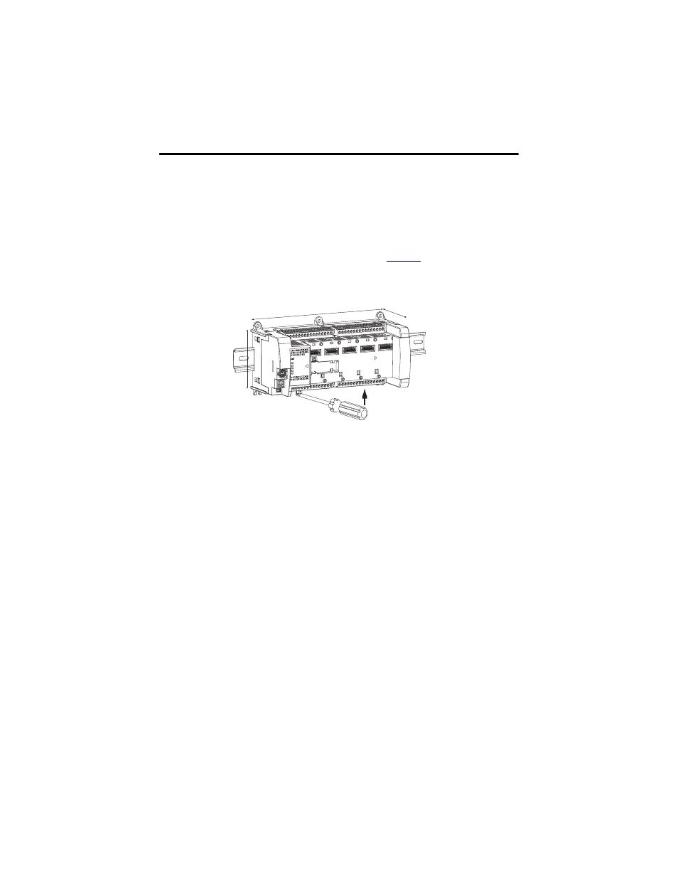
DIN Rail Mounting
The module can be mounted using the following DIN rails: 35 x 7.5 mm x 1 mm
(EN 50 022 - 35 x 7.5).
Before mounting the module on a DIN rail, use a flat-blade screwdriver in the DIN rail latch and
pry it downwards until it is in the unlatched position.
TIP
For environments with greater vibration and shock concerns, use the panel
mounting method, instead of DIN rail mounting.
45038
230 mm (9.05 in.)
80 mm (3.15 in.)
90 mm (3.54 in.)
Mounting dimensions do not include mounting feet or DIN rail latches.