E - doc – Rockwell Automation 2030-MLXxxx-SYSx System Multiplexer / Permissive Module User Manual
Page 7
(7)
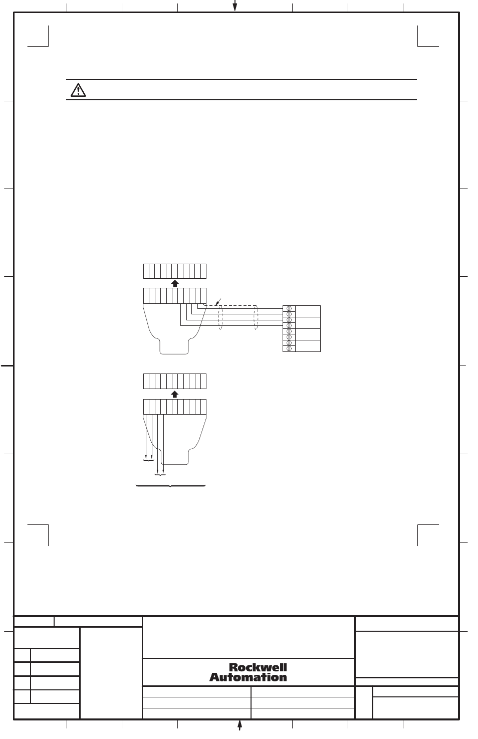
Figure 8
Wiring the System Multiplexer / Permissive Module to the PLC
1 2 3 4 5 6 7 8 9 10
G
N
D
1 2 3 4 5 6 7 8 9 10
G
N
D
1 2 3 4 5 6 7 8 9 10
G
N
D
1 2 3 4 5 6 7 8 9 10
G
N
D
Output 1
N
N
P
P
Output 2
PER1
Terminal Block
PLC
Terminal Block
Drain Wire
PER1
Connector Plug
Figure 9
Wiring the System Multiplexer / Permissive Module to the PLC
SR1
SR7
Output Status
PER1
Terminal Block
PER1
Connector Plug
Section 4
Wiring the Permissive Option to the PLC (PER1)
Sequence of events for System Multiplexer / Permissive Module option:
1. The PLC outputs are connected to the System Multiplexer / Permissive Module terminals PER1 (7) and (8) and PER1 (9) and (10), see Figure 8.
The outputs must be pulsed at a rate of 10 - 200Hz with a duty cycle of 10 - 90%. This signal is used by the System Multiplexer / Permissive Module
as a "heart beat" which holds the output of the System Multiplexer / permissive Module in the "ON" or closed state. Thus holding the ElectroGuard
®
system in the "ON" or Non-isolated state.
2. When a RLS is turned OFF, a signal is transmitted to the control system via a PLC connection on the RLS auxiliary contacts. Note that the outputs
of the System Multiplexer / Permissive Module remain in the "ON" or closed state.
3. When the customer's control system is at a predetermined stopping point, the control system, via the PLC outputs are turned to an off state (no heart
beat) and the outputs of the System Multiplexer / Permissive Module are then switched to the "OFF" or open state.
4. The system isolation function is then initiated on all of the ElectroGuard
®
systems simultaneously.
5. When all of the ElectroGuard
®
systems are in the isolated state, the System Multiplexer / Permissive Module sends the "Isolated" signal to the RLS
and the RLS System Isolated pilot light on the RLS will be illuminated. The RLS now has control of the ElectroGuard
®
and the energy can only be
restored to the machine or process by switching all of the RLSs connected to the multiplexers to the "on" state.
The output status of safety relay SR1 can be monitored on connector plug PER1 terminals 1 and 2 (see Figure 9). When the System Multiplexer /
Permissive Module is instructing the ElectroGuard
®
systems to "Isolate", a set of contacts will open between terminals PER1 (1) and (2).
The output status of safety relay SR7 can be monitored on connector plug PER1 terminals 3 and 4 (see Figure 9). When the PLC is allowing the
ElectroGuard
®
systems to "Isolate", a set of contacts will close between terminals PER1 (3) and (4).
ATTENTION: Hazardous Voltage; Voltage from sources other than the ElectoGuard
®
may be present on the PER1.
7
8
SYSTEM MULTIPLEXER / PERMISSIVE MODULE
INSTALLATION INSTRUCTIONS
1
1024403
42052-164
OF
N/A
N/A
N/A
REVISION
AUTHORIZATION
DR.
CHKD.
APPD.
DATE
DATE
DATE
E - DOC
LOCATION: MILWAUKEE, WISCONSIN U.S.A.
B-vertical.ai
DWG.
SIZE
SHEET
B
1
2
3
4
5
6
7
8
A
B
C
D
E
F
G
H
REFERENCE
DIMENSIONS APPLY BEFORE
SURFACE TREATMENT
(DIMENSIONS IN INCHES)
TOLERANCES UNLESS
OTHERWISE SPECIFIED
.XX:
.XXX:
ANGLES:
42052
---------------
---------
---------
---------
---------------
---------------
THIS DRAWING IS THE PROPERTY OF
ROCKWELL AUTOMATION, INC.
OR ITS SUBSIDIARIES AND MAY NOT BE COPIED,
USED OR DISCLOSED FOR ANY PURPOSE
EXCEPT AS AUTHORIZED IN WRITING BY
ROCKWELL AUTOMATION, INC.