E - doc – Rockwell Automation 2030-MLXxxx-SYSx System Multiplexer / Permissive Module User Manual
Page 4
Section 2 (Cont'd)
Installation of an System Multiplexer / Permissive Module
(4)
ATTENTION
: Hazardous voltage may be present on the load terminals of the ElectroGuard® Power Panel when the System Isolated Light is illuminated
under the following conditions:
·
The System Multiplexer is in a Master - Slave (series) configuration.
·
RLS(s) are connected to both the master and Slave System Multiplexers.
In this configuration clearly identify the power panel(s) that are being controlled by each RLS.
IMPORTANT: The EXB1 connector must be connected to the Control Module in one of ElectroGuard® Systems connected to the System Multiplexer /
Permissive Module. The System Multiplexer / Permissive Module derives its control power through the EXB1 connector.
IMPORTANT: The System Multiplexer / Permissive Module can accomodate up to a maximum of 6 RLSs. If less than the maximum number of RLSs is
needed for the installation, the unused RLS connectors must be jumpered out. The jumpers are necessary to simulate an RLS in the ON position. For example, if
RLS S#_F is not needed:
1) Remove RLS Plug, firmly grip the strain relief pad holding the RLS S#_F.
2) Remove the connector by pulling it away from the System Multiplexer / Permissive Module.
3) Once the jumpers are installed, re-insert the connector plug into the System Multiplexer / Permissive Module.
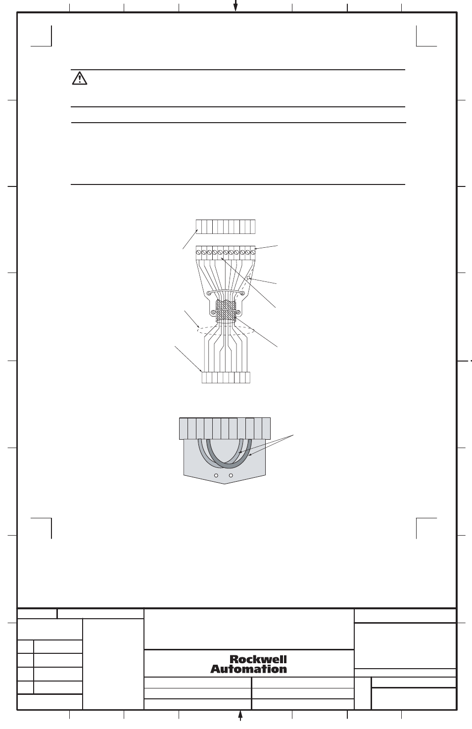
Select the RLS port and connector plug on the System Multiplexer / Permissive Module to be dedicated to the RLS being installed. Remove
these plugs by firmly grasping their strain relief tabs and pulling straight from the port. Wire each terminal block to its corresponding plug
using appropriate cable (see Figure 3).
Figure 3
Remote Lockout Station Wiring at System Multiplexer / Permissive Module
Factory installed jumper wires. These two
wires MUST be removed when wiring an
RLS to the connector plug
(RLS1 to RLS6) or (RLS_A to RLS_F)
RLS Connector Port Terminals in
Control Module or System
Multiplexer / Permissive Module
Drain Wire
The fifth terminal of the
Connector Plug is not used
for RLS connection
Braided Cable Shield
Terminal Block
Inside Remote
Lockout Station
Color Coded
Cable Recommended
RLS Connector Port Terminals
in Control Module or System
Multiplexer / Permissive
Module
1 2 3 4
6 7 8 9
G
N
D
1 2 3 4
5 6 7 8 9
1
0
G
N
D
Figure 4
RLS Connector Plug Jumper Wire
Locations
RLS Connector Plug
1 2 3 4 5 6 7 8 9 10 11
SYSTEM MULTIPLEXER / PERMISSIVE MODULE
INSTALLATION INSTRUCTIONS
1
1024403
42052-164
OF
N/A
N/A
N/A
REVISION
AUTHORIZATION
DR.
CHKD.
APPD.
DATE
DATE
DATE
E - DOC
LOCATION: MILWAUKEE, WISCONSIN U.S.A.
B-vertical.ai
DWG.
SIZE
SHEET
B
1
2
3
4
5
6
7
8
A
B
C
D
E
F
G
H
REFERENCE
DIMENSIONS APPLY BEFORE
SURFACE TREATMENT
(DIMENSIONS IN INCHES)
TOLERANCES UNLESS
OTHERWISE SPECIFIED
.XX:
.XXX:
ANGLES:
42052
---------------
----------
----------
----------
---------------
---------------
4
8
THIS DRAWING IS THE PROPERTY OF
ROCKWELL AUTOMATION, INC.
OR ITS SUBSIDIARIES AND MAY NOT BE COPIED,
USED OR DISCLOSED FOR ANY PURPOSE
EXCEPT AS AUTHORIZED IN WRITING BY
ROCKWELL AUTOMATION, INC.