E - doc – Rockwell Automation 2030-MLXxxx-SYSx System Multiplexer / Permissive Module User Manual
Page 5
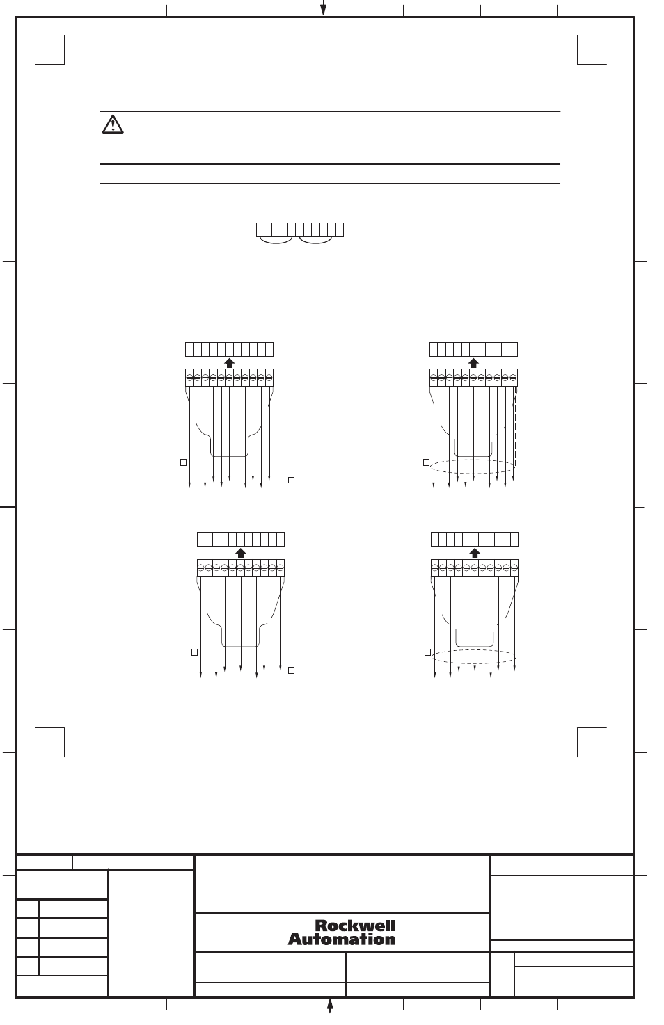
ATTENTION
: Hazardous voltage may be present on the load terminals of the ElectroGuard® Power Panel when the System Isolated Light is illuminated if
the jumper wires (see Figure 5) are not removed when multiple Power Panels are connected. The EXB2 thru EXB4 connector plugs provided on the
System Multiplexer / Permissive Module are factory shipped with two jumper wires installed (see Figure 5). These two jumper wires must be removed
and discarded when wiring is performed to connect an ElectroGuard® Power Panel. Failure to remove the two jumper wires will cause the System
Multiplexer / Permissive Module not to receive the proper system isolated status signals from the Power Panels and the System Isolated light may
illuminate when all power Panels have not gone to the isolated state.
IMPORTANT: The EXB1 connector must be connected to the Control Module in one of ElectroGuard
®
Systems connected to the System Multiplexer /
Permissive Module. The System Multiplexer / Permissive Module derives its control power through the EXB1 connector.
(5)
Section 3
Wiring the System Multiplexer / Permissive Module to the Control Module (EXB1 Connectors)
1 2 3 4 5 6 7 8 9 10 G
1. Select wire size to connect the System Multiplexer / Permissive Module to the Control Module or to series connect an System Multiplexer
Module based upon Table 3.
2. Install the interconnecting wiring between the EXB connector plug on the System Multiplexer / Permissive Module and the RLS connector
plug selected for connection to the Control Module (see Figures 6). When series connecting the System Multiplexer Module, install the
interconnecting wiring between the EXB2, 3 or 4 connector plug to the RLS_A connector plug on the series connected System Multiplexer
Module.
GND
TO RLS (10)
TO RLS (9)
TO RLS (8)
TO RLS (6)
TO RLS (5)
TO RLS (4)
TO RLS (3)
TO RLS (1)
1 2 3 4 5 6 7 8 9 10 G
GND
FROM EXB1 (10)
FROM EXB1 (9)
FROM EXB1 (8)
FROM EXB1 (6)
FROM EXB1 (5)
FROM EXB1 (4)
FROM EXB1 (3)
FROM EXB1 (1)
EXB1 Terminal Block
on System Multiplexer /
Permissive Module
EXB1 Connector Plug
on System Multiplexer /
Permissive Module
EXB_ Connector Plug
on System Multiplexer /
Permissive Module
RLS Terminal Block
on Control Module
Indicates Connection Point
on Connection Plug
Any RLS Port on Control Module
RLS Connector Plug
on Control Module
RLS Terminal Block
on Control Module
RLS Connector Plug
on Control Module
1
1
1
Shield
Figure 6A
Wiring the System Multiplexer / Permissive Module
EXB1 Connector Plug to the Control Module
Figure 5
EXB2-4 Connector Pug Jumper Wire Locations
1 2 3 4 5 6 7 8 9 10 G
GND
TO RLS (9)
TO RLS (8)
TO RLS (6)
TO RLS (4)
TO RLS (3)
TO RLS (1)
1 2 3 4 5 6 7 8 9 10 G
GND
FROM EXB_ (9)
FROM EXB_ (8)
FROM EXB_ (6)
FROM EXB_ (4)
FROM EXB_ (3)
FROM EXB_ (1)
EXB_ Terminal Block
on System Multiplexer /
Permissive Module
Indicates Connection Point
on Connection Plug
Any RLS Port on Control Module
1
1
1
Shield
Figure 6B
Wiring the System Multiplexer / Permissive Module
EXB2 thru EXB4 Connector Plug to the Control Module
1 2 3 4 5 6 7 8 9 10 G
EXB2 thru EXB4 Connector Plugs
5
8
SYSTEM MULTIPLEXER / PERMISSIVE MODULE
INSTALLATION INSTRUCTIONS
1
1024403
42052-164
OF
N/A
N/A
N/A
REVISION
AUTHORIZATION
DR.
CHKD.
APPD.
DATE
DATE
DATE
E - DOC
LOCATION: MILWAUKEE, WISCONSIN U.S.A.
B-vertical.ai
DWG.
SIZE
SHEET
B
1
2
3
4
5
6
7
8
A
B
C
D
E
F
G
H
REFERENCE
DIMENSIONS APPLY BEFORE
SURFACE TREATMENT
(DIMENSIONS IN INCHES)
TOLERANCES UNLESS
OTHERWISE SPECIFIED
.XX:
.XXX:
ANGLES:
42052
---------------
---------
---------
---------
---------------
---------------
THIS DRAWING IS THE PROPERTY OF
ROCKWELL AUTOMATION, INC.
OR ITS SUBSIDIARIES AND MAY NOT BE COPIED,
USED OR DISCLOSED FOR ANY PURPOSE
EXCEPT AS AUTHORIZED IN WRITING BY
ROCKWELL AUTOMATION, INC.