Install the terminal, Mounting clearances, Mount the terminal in a panel – Rockwell Automation 2711PC-x6xxxx PanelView Plus 400 and 600 Terminals Installation Instructions User Manual
Page 10: Panel cutout dimensions
10 PanelView Plus and PanelView Plus Compact 400 and 600 Terminals
Publication 2711P-IN002G-EN-P - November 2009
Install the Terminal
Before installing the terminal in a panel, review these topics:
•
Mounting clearances
•
Panel cutout dimensions
•
Product dimensions
Mounting Clearances
Allow adequate clearance around the terminal, inside the enclosure, for adequate ventilation.
Consider heat produced by other devices in the enclosure. The ambient temperature around
the terminals must be between 0…55 °C (32…131 °F).
Minimum clearances for ventilation are:
•
Top clearance: 51 mm (2 in.)
•
Bottom clearance: 102 mm (4 in.)
•
Side clearances: 25 mm (1 in.)
•
Back clearance: 0 mm (0 in.)
Minimum side clearance for insertion of memory card is 102 mm (4 in.).
Panel Cutout Dimensions
Use the full size template shipped with your terminal to mark the cutout dimensions.
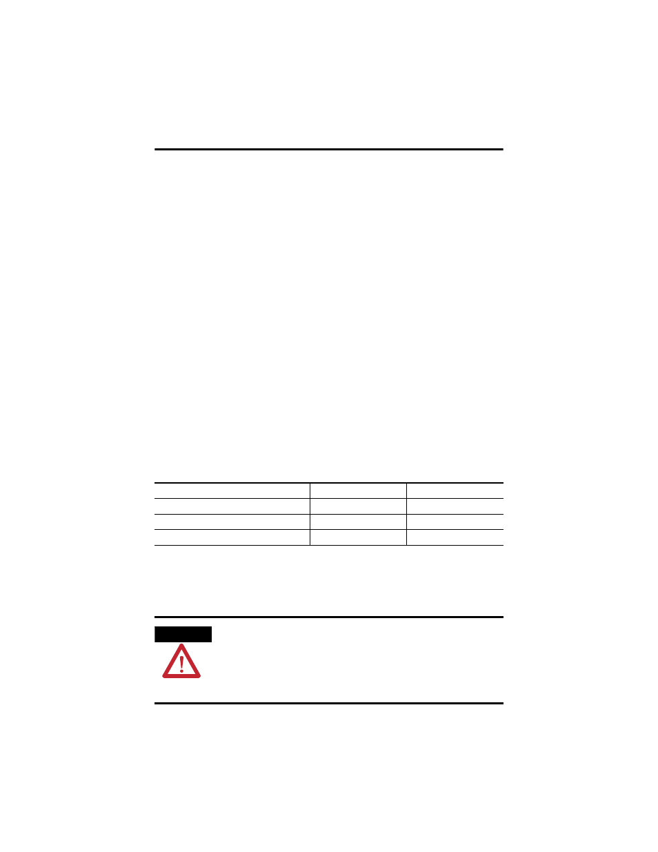
Mount the Terminal in a Panel
Mounting levers secure the terminal to the panel. The number of levers you use
(4 or 6) varies by terminal type.
Terminal Type
Height, mm (in.)
Width, mm (in.)
400 Keypad or Keypad and Touch
123 (4.86)
156 (6.15)
600 Keypad or Keypad and Touch
142 (5.61)
241 (9.50)
600 Touch
123 (4.86)
156 (6.15)
ATTENTION
Disconnect all electrical power from the panel before making the panel cutout.
Make sure the area around the panel cutout is clear.
Take precautions so metal cuttings do not enter any components already installed in
the panel.
Failure to follow these instructions may result in personal injury or damage to panel
components.