Connect the board – Rockwell Automation 1799-D10U10BL 10 Input/10 Output Discrete Embedded I/O User Manual
Page 7
10 Input/10 Output Discrete Embedded I/O Boards 7
Publication 1799-IN003B-EN-P - December 2000
Connect the Board
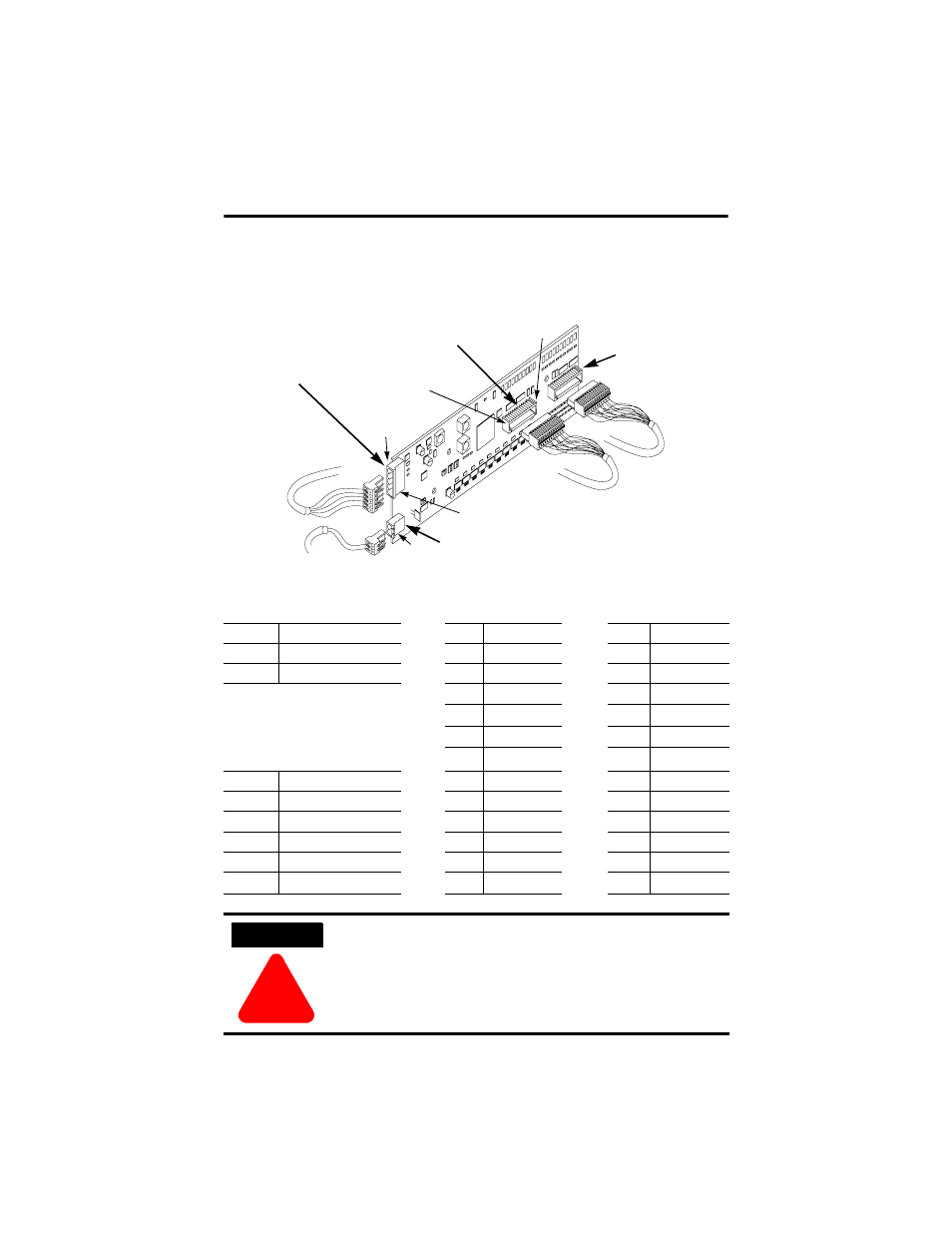
Use the following picture and tables to help you connect the DeviceNet,
auxiliary power, and I/O connectors to the board.
The following tables identify the pins of each connector.
P1 Auxiliary Power Connector
P3 I/O Connector
P4 I/O Connector
Pin
Signal
Pin
Signal
Pin
Signal
1
24V dc
1
Output 0
1
Input 0
2
24V dc Ret
2
Output 1
2
Input 1
3
Output 2
3
Input 2
4
24V dc Ret
4
In Common
5
Output 3
5
Input 3
P2 DeviceNet Connector
6
Output 4
6
Input 4
Pin
Insulation Colors
7
Output 5
7
Input 5
1
Black
8
Output 6
8
Input 6
2
Blue
9
24V dc
9
In Common
3
Shield
10
Output 7
10
Input 7
4
White
11
Output 8
11
Input 8
5
Red
12
Output 9
12
Input 9
ATTENTION
!
•
For maximum noise immunity, input cable return wires must be
properly terminated.
•
When inputs are connected in loopback, return wires should be
connected together.
•
I/O cable length should be less than 30 meters (98.43 feet).
I/O Connector (P4)
I/O Connector (P3)
Auxiliary Power Connector (P1)
DeviceNet Connector (P2)
42508
Pin 5
(bottom)
Pin 1
(top)
Pin 12 (right)
Pin 1 (left)
Pin 2 (bottom)