Physically installing the drive & at your site, Inspecting the air baffles, Preparing ac input entry – Rockwell Automation 1395 Digital DC Drive User Manual
Page 56: Physically installing the drive at your site -2, Inspecting the air baffles -2, Preparing ac input entry -2, Physically installing the drive, At your site
Publication 2361-5.01 July 1998
Installing Your Drive
Physically Installing the Drive
&
at Your Site
To move and position the unit at your site, you will need to follow the
instructions given in Publication 2100-5.5, titled Receiving,
Handling, And Storing Motor Control Centers–Instructions. This
publication will instruct you in the proper handling, moving, and
positioning of your new drive.
&
After the drive is properly positioned, follow the instructions given in
Publication 2300-5.1, titled Bulletin 2300 Family of Drive Systems
Hardware–Installation Manual. This publication will teach you how
to splice busbars, how to attach your unit in a multiple drive
configuration, and how to join MCC sections together (if necessary).
Inspecting the Air Baffles
Inspect the air baffles and guards according to the air baffle layouts
shown in Appendix A.
Preparing AC Input Entry
If your drive has an extra input bay installed, you can skip this
section.
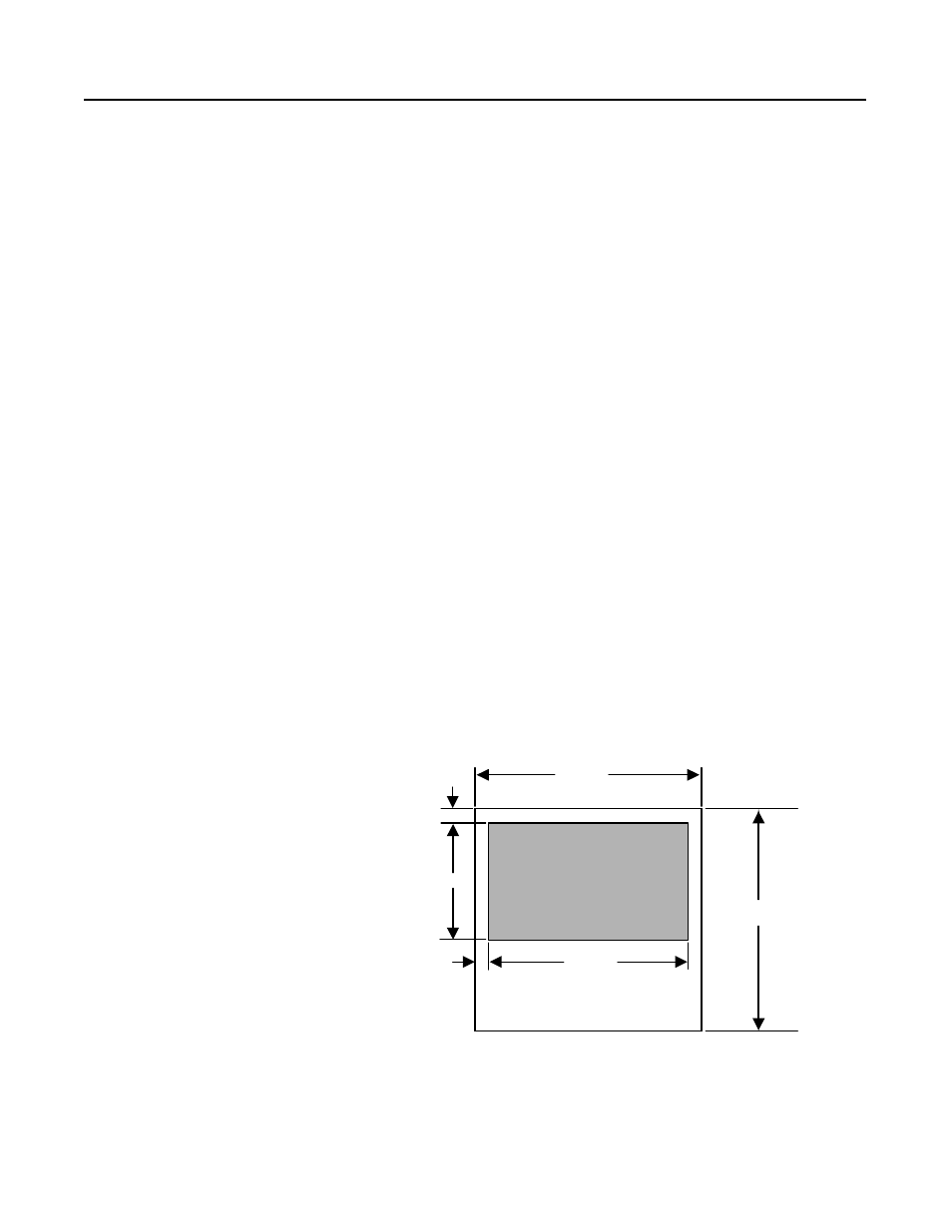
To prepare input entry, select the ideal hole placement (within the
constraints of the following diagram), then follow the installation
steps given. The following instructions include directions for a top
hat assembly.
Note: When preparing the input entry, you may need to consider
the busbar arrangement and the wire sizes. Busbar diagrams are
shown in Appendix A, and recommended wire sizes are listed
later in this chapter.
Figure 5.1
Area Available For Conduit Entry (Top View of Disconnect Bay)
3000A units allow a depth of 16.75" for conduit entry.
(Back of Enclosure)
Area Available For
Conduit Entry
1.14"
17.72"
20.00"
20.00"
1.25"
11.50"
(Front of Enclosure)