Power stage interface board, Power stage interface board -8, Figure 1.5 power stage interface board – Rockwell Automation 1395 Digital DC Drive User Manual
Page 20: 8 product overview
Publication 2361-5.01 July 1998
1-8
Product Overview
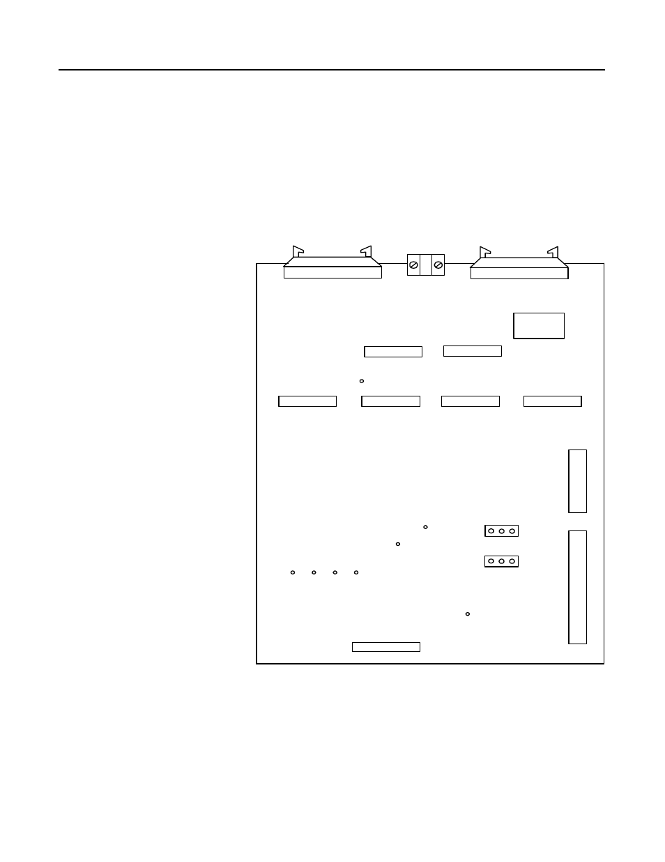
Power Stage Interface Board
The power stage interface board is used as the chief interface between
the main control board and other boards of the system. This board is
responsible for distributing power and control signals to and from the
main control board, gate interface board, field-pulse transformer
board, feedback board, and unit power supply. Refer to Figure 1.1 to
see how this board is connected in the drive.
Figure 1.5
Power Stage Interface Board
&
The test points and jumpers shown in the diagram are used for startup
and troubleshooting procedures. Refer to the troubleshooting manual
for more information on test points and jumpers.
J 3D
J 2
J 6
J 7
J1
J1 0
J 8
J 9
C o nn e ctio n to M a in Co n tro l Bo a rd
C o nn e ctio n to M a in Co n tro l Bo a rd
C o nn e ctio ns to
G a te Inte rfa ce B o a rd
Co n ne ctio n to
F e e db a ck B o a rd
Co n ne c tio n to
F ie ld Tra n sfo rm e r
C o n ne ctio n to
U n it P ow e r S u pp ly
J 3C
J 3B
J3 A
T B 1
TP 8
(-1 2 V)
T P 7
(G nd )
T P 6
(+ 1 2 V )
T P 5
(+ 5 V)
T P 9
TP 1
(+ 2 4 V )
TP 3
T P 2
J 12
J 11
C o nn e ctio n to
M a in C o nta cto r, P ilo t R e la y,
a nd U nit P o w e r S up ply
C o nn e cte d to T B 3
(S ta nd a rd In te rfac e )
C o nn e ctio n to U n it P o w e r
S up ply a nd T E