Figure 1.10 armature bridge (regenerative), Product overview 1-15 – Rockwell Automation 1395 Digital DC Drive User Manual
Page 27
Publication 2361-5.01 July 1998
Product Overview
1-15
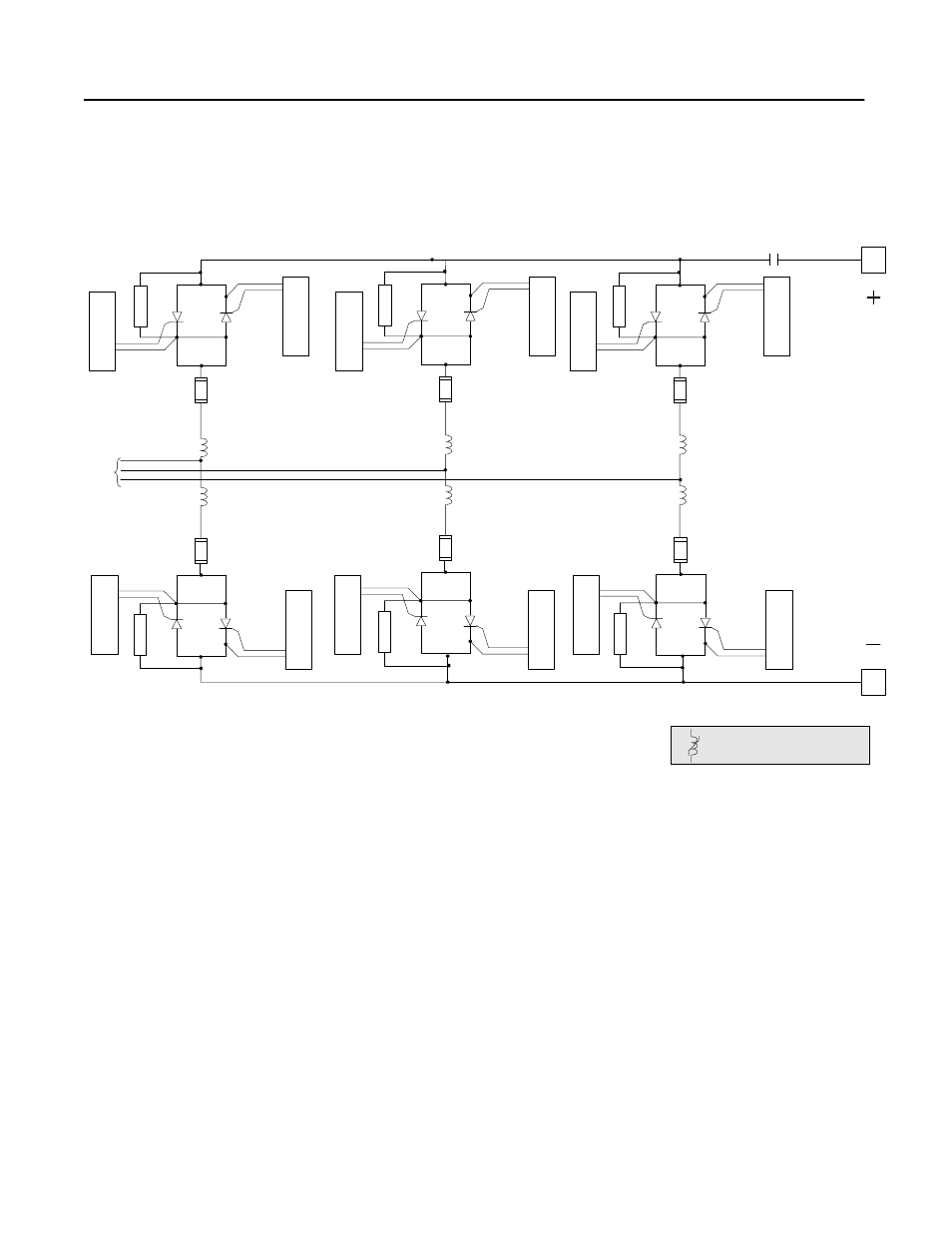
The regenerative bridge, shown in Figure 1.10, allows the bridge to
regenerate, or to direct power backwards onto the incoming lines.
Figure 1.10
Armature Bridge (Regenerative)
Silicon-Controlled Rectifiers (SCRs)
Each drive uses silicon-controlled rectifiers (SCRs) in the thyristor
bridge to switch the incoming 3-phase AC power to DC output
power.
These SCRs allow current to flow from anode to cathode when two
conditions are met. First, like a diode, it must be forward biased.
Second, an appropriate pulse must be applied to the gate (through the
pulse transformer board).
The current will continue through the SCR until the voltage across it
reverses and the current drops to zero (called line commutation).
Figure 1.11 shows a picture of an SCR, depicting its polarity.
A1
A rm ature
Voltag e
3-P hase
A C
Input
M ain
Contactor
A2
S
N
UBB
E
R
S
N
UBB
E
R
S
N
U
BBE
R
S
N
UB
BE
R
Ar
ma
tu
re
-P
ul
se
T
ran
sf
orm
e
r Boa
rd
Ar
m
a
tu
re
-P
ul
se
T
ran
sf
orm
e
r Bo
ard
Ar
ma
tu
re
-P
ul
se
T
ran
sf
orm
e
r Boa
rd
Ar
m
a
tu
re
-P
ul
se
T
ran
sf
orm
e
r Bo
ard
Ar
m
at
u
re
-P
u
ls
e
T
ra
n
sform
er B
oard
Ar
m
at
u
re
-P
ul
se
T
ran
sfor
m
er Boar
d
Ar
m
at
u
re
-P
u
ls
e
T
ra
n
sform
er B
oard
Ar
m
at
u
re
-P
ul
se
T
ran
sfor
m
er Boar
d
S
N
UBB
E
R
S
N
UBB
E
R
Ar
ma
tu
re
-P
ul
se
T
ran
sf
orm
e
r Boa
rd
Ar
m
a
tu
re
-P
ul
se
T
ran
sf
orm
e
r Bo
ard
Ar
m
at
u
re
-P
u
ls
e
T
ra
n
sform
er B
oard
Ar
m
at
u
re
-P
ul
se
T
ran
sfor
m
er Boar
d
The 30 00 A unit us es s olid co re (ferrite )
chokes on the A C line.