Setting the crimp value, Crimping a contact – Rockwell Automation 2090-Series Circular-DIN Connector Kits, Flange Kits, and Crimp Tools User Manual
Page 6
Rockwell Automation Publication 2090-IN042A-EN-P - May 2011
6
Setting the Crimp Value
For crimp depth setting and positioning insert selection, see
.
The values in the table are for standard fine stranded copper wires. The values
serve as reference only and must be verified with a pull test according to
olderless Connections. Crimped Connections. General
Requirements, Test Methods and Practical Guidance), Table 4, using the actual
wire.
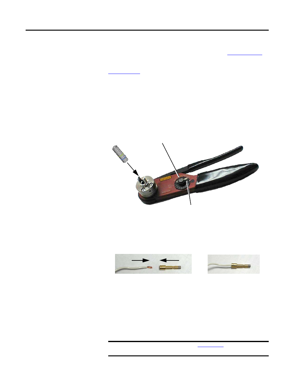
1. Insert the positioning insert into the crimp tool.
2. Remove the crimp setting lock pin.
3. Lift the crimp setting dial and turn to the desired crimp setting.
4. Replace the crimp setting lock pin.
Crimping a Contact
1. Insert the wire into the contact (actual contacts will vary).
2. Feed the contact and wire as far as possible through the indenters to the
stop in the positioning insert.
3. Close the crimp tool handles all the way, and then release the handles to
allow the crimp tool to open.
Note: If the crimp tool does not open, the handles were not closed far
enough for the crimp to be successful. Continue to close the handles until
the crimp tool is able to open.
4. Remove the wire and contact from the positioning insert.
IMPORTANT
Perform a pull test according to
, Table 4, for the first
crimp, and periodically throughout multiple crimpings.
Crimp Setting Dial
(Pull dial up and turn to desired crimp setting.)
Crimp Setting Lock Pin
(Remove pin to set crimp setting, then replace pin to lock setting.)
Positioning
Insert