Setting the crimp value – Rockwell Automation 2090-Series Circular-DIN Connector Kits, Flange Kits, and Crimp Tools User Manual
Page 15
Rockwell Automation Publication 2090-IN042A-EN-P - May 2011
15
Setting the Crimp Value
and
21
for crimp depth setting and locator selection. The
values in the table are for standard fine stranded copper wires. The values serve as
reference only and must be verified with a pull test according to
(Solderless Connections. Crimped Connections. General
Requirements, Test Methods and Practical Guidance), Table 4, using the actual
wire.
1. Loosen the adjustment wheel setscrew.
2. Set the crimp value by turning the adjustment wheel until the digital
display shows the required value.
Note: Turn the adjustment wheel clockwise to reduce the crimp value, and
counterclockwise to increase the crimp value.
3. Use an Allen wrench to tighten the adjustment wheel setscrew to save the
settings.
4. If necessary, pull up on the locator until the spring-loaded cartridge that is
locked in place is released.
5.
and
21
to determine the correct locator selection.
6. Turn the locator to align the desired locator cartridge with the crimp
indenters, then press in the locator cartridge until it snaps into place.
IMPORTANT
For accuracy when setting the crimp value, always turn the adjustment
wheel from a larger number to the actual setting. For example, turn the
adjustment wheel up to 2.10 mm and then turn the adjustment wheel
down to 2.00 mm. Do not start at 1.90 mm and turn the adjustment wheel
up to 2.00 mm.
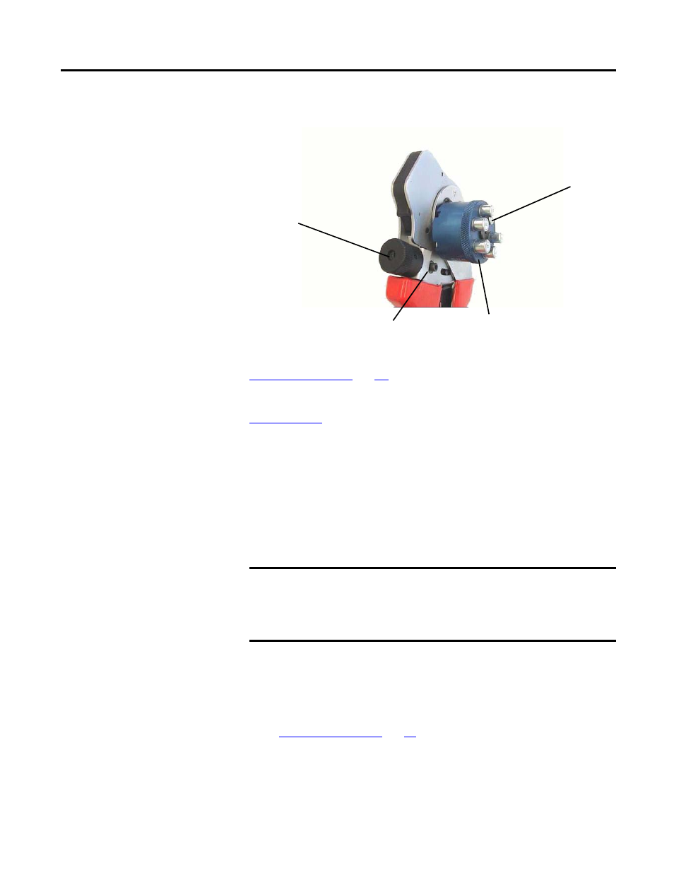
Turn Locator Until Desired Cartridge
is Positioned Over Crimp Indenters
Adjustment Wheel
Setscrew
Press in
Locator
Cartridge
Turn the
Adjustment
Wheel to
Set Crimp
Value