Dip switch settings (slave versions), Additional information – Rockwell Automation 2706-LV2xX, -LV4xX Dataliner DL40 Plus Message Display Installation User Manual
Page 7
Dataliner DL40 Plus Message Display (Catalog No. 2706-LV2xX, -LV4xX)
7
DIP Switch Settings
(Slave Versions)
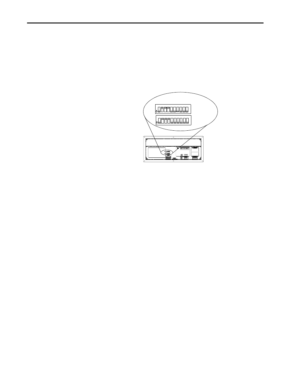
Access the 10-position DIP switches from the back of the display. Set DIP
switches using a thin nonconductive object. Do not use a pencil (broken
graphite pieces may short out the internal circuitry).
Changes to DIP switches take effect on powerup. The DL40 Plus slave
displays the current settings during its powerup sequence. If you make
changes with the power applied, you will have to cycle power before the
changes take effect. For details on setting DIP switches, refer to the DL40
Plus Slave User Manual (Publication 2706-6.3).
Positions #1 and #2 of DIP Switch #1 set the operating mode. Default
factory setting is DL Slave mode.
Positions #3 and #4 of DIP Switch #1 set the display language. Default
factory setting is English.
Positions #5 and #6 of DIP Switch #1 set the baud rate. Select the baud
rate to match the host device. Default factory setting is 9600.
Positions #7 and #8 of DIP Switch #1 determine the parity. Set the
parity to match the host device. Default factory setting is Even Parity
enabled. Positions #9 and #10 apply to Terminal mode operation.
Positions #1 through #7 of DIP Switch #2 select the serial address of
the DL40 Slave. The address is the binary sum of the value of all the
switches in the Up condition. Default factory setting is address 127.
Positions #8 to #10 are not used.
Additional Information
For additional information on communication port wiring and display
configuration, refer to the DL40 Plus User Manual (Publication 2706-6.1)
or DL40 Plus Slave User Manual (Publication 2706-6.3).
10-Position DIP Switch
↑
Up = ON
↓
Down = OFF
N
O
1 2 3 4
5 6 7 8 9 10
N
O
1 2 3 4
5 6 7 8 9 10