Dip switch settings (remote i/o versions), Power connections – Rockwell Automation 2706-LV2xX, -LV4xX Dataliner DL40 Plus Message Display Installation User Manual
Page 5
Dataliner DL40 Plus Message Display (Catalog No. 2706-LV2xX, -LV4xX)
5
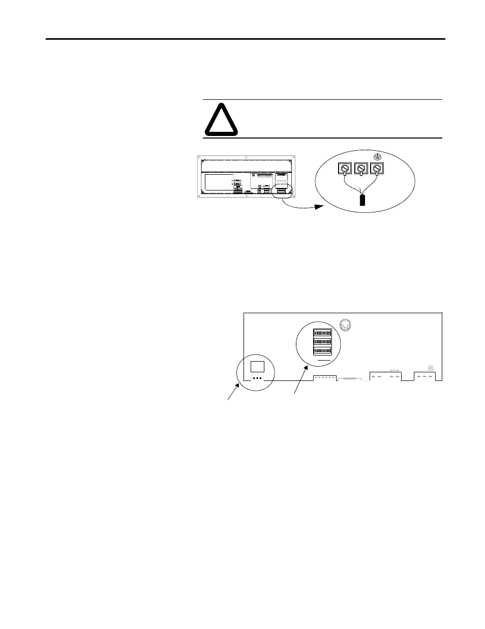
Power Connections
Before making power connections, make sure that the power is turned off.
The DL40 Plus display requires 100-240Volts AC, 50/60 Hz, 0.60-0.25
Amperes.
DIP Switch Settings
(Remote I/O Versions)
Three DIP switch banks are located on the back of the display. Access the
DIP switches through a cutout, as shown below. Set DIP switches using a
thin nonconductive object. Do not use a pencil (broken graphite pieces may
short out the internal circuitry).
For details on DIP switch settings, refer to the DL40 Plus User Manual
(Publication 2706-6.1).
Switch Bank #1 (SW-1) sets the rack address.
Switch Bank #2 (SW-2) controls Baud Rate, Fast Reset Sequence,
Block Transfer, Last Chassis, Keyboard Type, Handshaking, Last State,
Select Enable, No PLC Comm Error Message.
Switch Bank #3 (SW-3) sets the serial address. The serial address refers
to the address used for triggers received from the serial RS-485 port or
computer keyboard.
Important: Disconnect power from the DL40 Plus before setting any
switch except Select Enable, SW2-9. Select Enable can be changed with
the power on. Switch settings are scanned only on power-up. A new
setting for Select Enable takes effect immediately. All other switches take
effect on power-up or reset.
!
ATTENTION: Improper wiring of the power
connections may result in damage to the DL40.
Green
(Green/Yellow)
L2N
L1
Black
(Brown)
White
(Blue)
KEYBOARD
SW1
SW2
SW3
G
N
D
RELAY
L1 L2N
RIO
2 S 1
RS-485
250 VAC 3A
1
2
V
D
C
RS-232
Remote I/O Port
Location of DIP Switches