Power wiring requirements, Shunt module power wiring requirements, Shunt module jumper settings – Rockwell Automation 2094-BSP2 Kinetix 6000 Shunt Module Installation Instructions User Manual
Page 8: Col int dc+ ts2 ts1
8 Kinetix 6000 Shunt Module
Publication 2094-IN004E-EN-P — June 2008
Power Wiring Requirements
Shunt Module Power Wiring Requirements
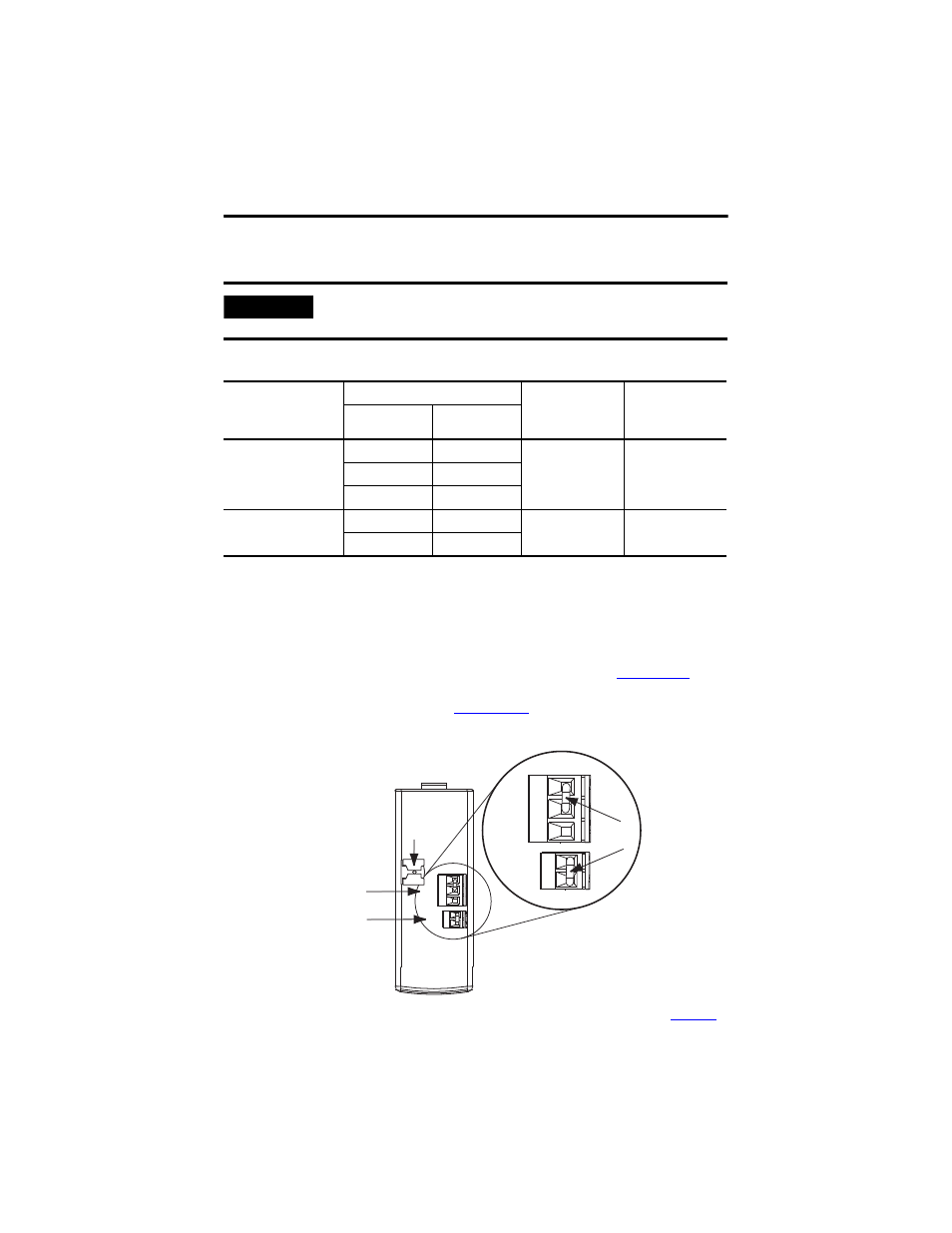
Using the default jumper settings, the Bulletin 2094 shunt module’s (200 W) internal
resistor is enabled and the thermal switch circuitry is not used. Remove the RC
connector jumper when wiring to a Bulletin 1394 external shunt module. Remove
the TS connector jumper when wiring to the 1394-SR36AF thermal-switch terminals.
Refer to the Kinetix Motion Control Selection Guide, publication
Bulletin 1394 shunt module catalog numbers. Refer to the Kinetix 6000 Multi-axis
Servo Drive User Manual, publication
connect diagrams.
Shunt Module Jumper Settings
(1)
These are the default jumper settings. Refer to External Shunt Modules Installation Instructions, publication
when removing these jumpers and wiring to a Bulletin 1394 external shunt module.
IMPORTANT
The National Electrical Code and local electrical codes take precedence over
the values and methods provided.
Connections
Terminals
Recommended
Wire Size
mm
2
(AWG)
Torque Value
N•m (lb•in)
Pin
Signal
1394-SRxxxx
External passive shunt
module
RC-1
DC+
10 (8)
(1)
(1)
105 °C (221 °F), 600V.
1.2…1.5
(10.6…13.2)
RC-2
INT
RC-3
COL
Thermal switch
TS-1
TS1
0.75 (18)
0.22…0.25
(1.9…2.2)
TS-2
TS2
1 2 3
1 2
1 2 3
1 2
COL
INT
DC+
TS2
TS1
COL
INT
DC+
TS2
TS1
External Shunt Resistor
(RC) Connector
2094-BSP2 Shunt Module
(top view)
External Thermal Switch
(TS) Connector
Cable Shield
Clamp
Jumpers
(1)