Programming the rgu – Rockwell Automation 2364P Parallel DC Bus Supply Config. User Manual
Page 194
Publication 2364P-5.01 December 1999
Setting Up the Parallel Configuration
Programming the RGU
Using a HIM, GPT, or other programming device, enter the linear
parameter list. The startup procedure below will guide you through
several parameters that need to be configured before operating the
parallel configuration. Program each RGU in the configuration.
Frame Catalog Number [P4]
Enter the frame catalog number of each RGU (this
should correspond to the catalog number shown on
the data name plate of the RGU, located below the
main control board.
RGU Control Mode [P5]
Set this parameter to the appropriate setting:
Master Mode (0) Use this setting if this is a master unit in a lineup of multiple RGUs.
Slave Mode (1)
Use this setting if this is a slave unit in a lineup of multiple RGUs.
Standalone (2)
Use this setting if there are no other RGUs in the lineup (default).
Remote/Local Selector [P8]
Set this parameter to the desired setting (Local Only is default):
Local Only (0)
Use this setting for automatic enabling at startup (HIM/GPT not used for
enable).
Remote+Local (1) Use this setting for manually enabling the RGU via a HIM or GPT.
AC Line Reactor Inductance [P12]
Determine the total line inductance. This is a sum of the RGU line inductance and the transformer
leakage inductance.
P12 = Line Inductance of single RGU + (Transformer Leakage Inductance x #RGUs)
The RGU line inductance values are given below.
For transformer leakage inductance, use the following formulas.
Example
A parallel configuration (catalog number 2364PA-T5B)
is supplied with a transformer which has the example
nameplate shown.
In Appendix B, we find that the catalog number
(2364PA-T5B) indicates the has two 460V AC M-code RGUs.
The line reactors for these units are rated at 137 uH as indicated in the chart above.
To determine the transformer leakage inductance, we can use the 60Hz formula with the
information from the data nameplate.
Add the total line reactor inductance of a single RGU to the transformer leakage inductance times
the number of RGUs to determine the value for P12.
P12 = 137uH + (28uH x 2) = 193uH
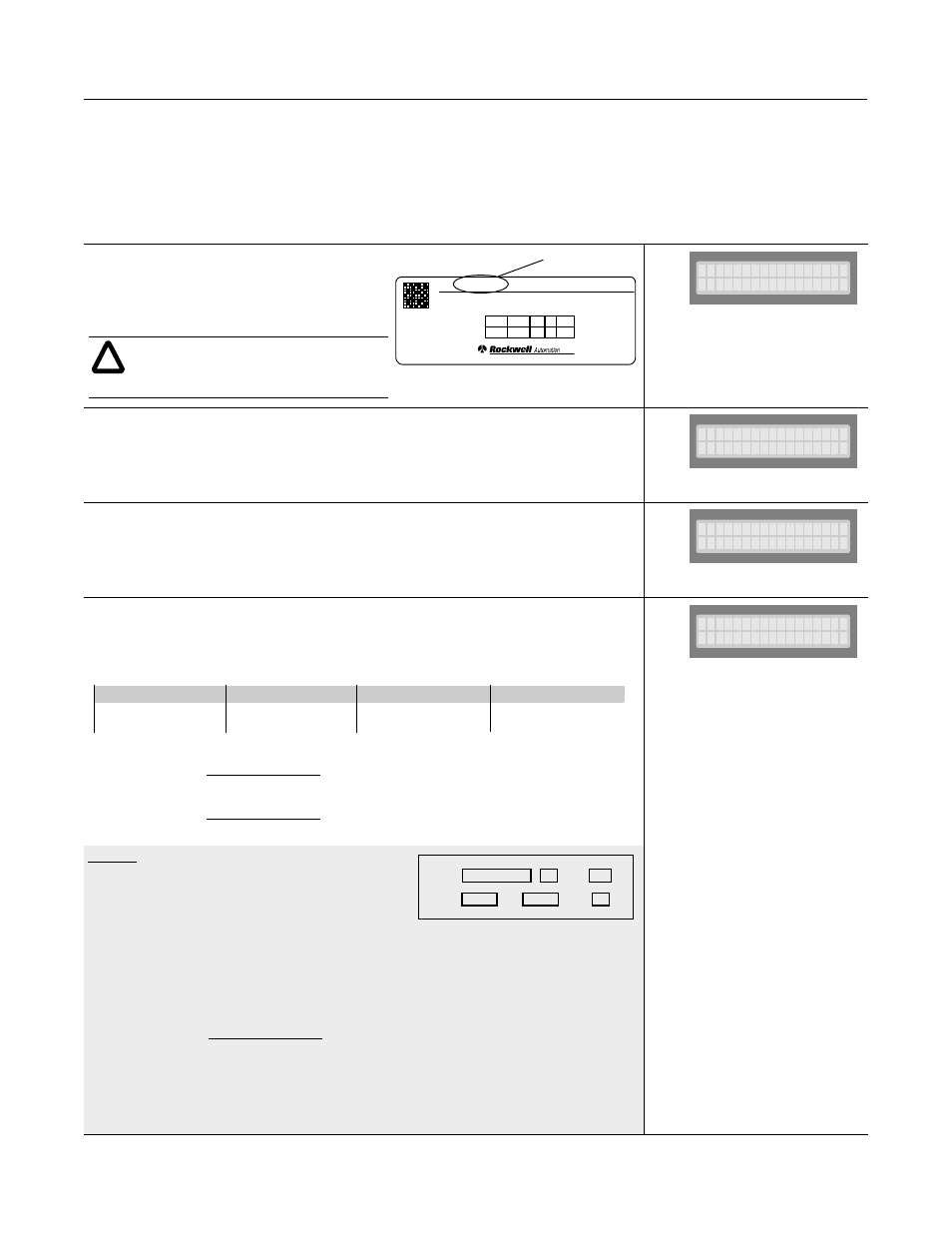
AC INPUT
DC OUTPUT
MADE IN U.S.A.
CAT
2364FA-MNB
SER B
Refer to user manual for
installation instructions
CONSTANT TORQUE
Drive Systems
541
460
678
3
50/60
524
683
749
-
DC
VOLTS
A
Hz
KVA
PH
Catalog Number
!
ATTENTION: Changing P4 will reinitialize
all parameters in the RGU and will configure
several key parameters to the catalog number
selected.
2364F- MNB
RGU Cat al og #
St andal one
RGU Cont r ol
Mode
Remot e+Local
Rem/ Loc Sel ect or
Factory
Default
510 (380/460V)
832 (575V)
K-code RGUs
Factory
Default
317 (380/460V)
404 (575V)
L-code RGUs
Factory
Default
137 (380/460V)
191 (575V)
M-code RGUs
Factory
Default
102 (380/460V)
144 (575V)
N-code RGUs
(at 60Hz)
(at 50Hz)
Iz Leakage Reactance (%) of Transformer
Vrms Voltage rating (rms) of transformer
kVA Transformer size
Leakage Inductance
of Transformer (uH)
=
2.65 x Iz x Vrms x Vrms
kVA
Leakage Inductance
of Transformer (uH)
=
3.18 x Iz x Vrms x Vrms
kVA
165 uH
Li ne I nduct ance
Catalog No.
Phase
Hz
kVA
Vrms
%Iz
TMR001-1
3
60
1000
460
5
Leakage Inductance
of Transformer
=
2.65 x 0.05 x 460 x 460
1000
=
28uH