Customer connections, Analog input/output (rgu main control board), Terminals description – Rockwell Automation 2364P Parallel DC Bus Supply Config. User Manual
Page 183
Publication 2364P-5.01 December 1999
Installation
Customer Connections
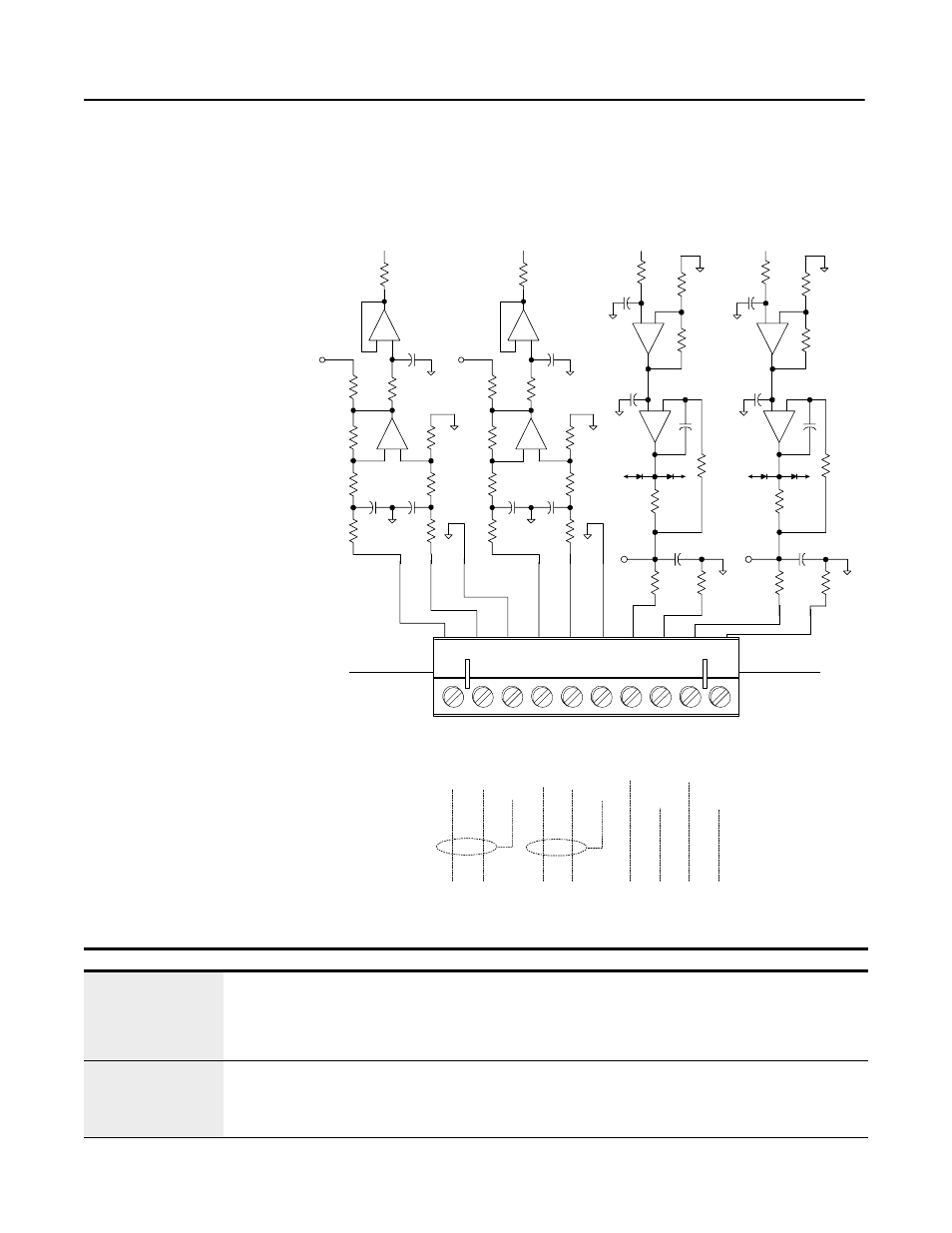
Analog Input/Output (RGU Main Control Board)
Analog input and output connections are available on TB1 of the
main control board (RGU).
Figure 15.10
Customer Connections–TB1 (RGU Main Control Board)
Table 15.A: Customer Connections–TB1 (RGU Main Control Board)
20k
0.04 7uf
0.04 7u f
20k
A GN D
20k
20k
20k
20k
- +
AG N D
1k
1k
T P27
.1
A GN D
- +
1k
A GN D
20k
0.04 7uf
0.0 47u f
20k
A G ND
20k
20k
20k
20k
- +
A GN D
1k
1k
T P28
.1
AG N D
- +
1k
A G ND
10
2200p f
10
AG N D
100
AG N D
T P30
-15V
+1 5V
+ -
.1
8.25k
+ -
10k
AG ND
4700p f
10k
10k
AG N D
560p f
10
2200p f
1 0
A GN D
1 00
A GN D
T P31
+ -
.1
8.25k
+ -
10k
AG N D
4700p f
10k
10k
A GN D
-15V
+ 15V
56 0pf
TB 1
1
2
3
4
5
6
7
8
9
10
An
a
lo
g
In
1
(
-)
A
n
al
og
In
1
(
+
)
A
n
al
og
I
n
1
(
C
mn
)
A
n
al
og
I
n
2
(
-)
A
n
al
og
I
n
2
(
+
)
A
n
al
og
In
2
(
C
mn
)
An
al
o
g
O
u
t 1
A
n
al
og
O
u
t 1
(
C
m
n
)
An
al
o
g
O
u
t 2
A
n
al
og
O
u
t 2
(
C
m
n
)
-10 V to + 1 0V
-10 V to + 1 0 V
-10 V to + 1 0 V -10 V to + 1 0V
Terminals
Description
TB1-1, TB1-2, TB1-3
TB1-4, TB1-5, TB1-6
Terminals TB1-1, 2, 3 are designated to Analog Input 1 and TB1-4, 5, 6 are designated to Analog Input 2. These can be
connected to a customer device which sends signals between ±10V. The analog voltage supplied is sampled by a 14-bit
analog-to-digital converter, and the resulting value is stored in parameter P36 (A/D Converter 0 Input). The internal circuitry
has an 80k differential input resistance and a 40k common-mode input resistance. 14AWG wiring is recommended for
customer connection.
TB1-7, TB1-8
TB1-9, TB1-10
Terminals TB1-7 and TB1-8 supply analog output from parameter P47 (D/A Converter 1 Output); TB1-9 and TB1-10 supply
analog output from parameter P48 (D/A Converter 2 Output). The RGU can be programmed to report parameter values (such
as trend parameters) to the customer device. The customer device must have a minimum 1k load resistance. 14AWG
wiring is recommended for customer connection.