Rockwell Automation 1799-D16U16BAGL 16 Input/16 Output Digital and 2 Input/2Output Analog User Manual
Page 16
16 16 Input/16 Output Digital and 2 Input/2 Output Analog Embedded I/O Boards
Publication 1799-IN011A-EN-P - February 2007
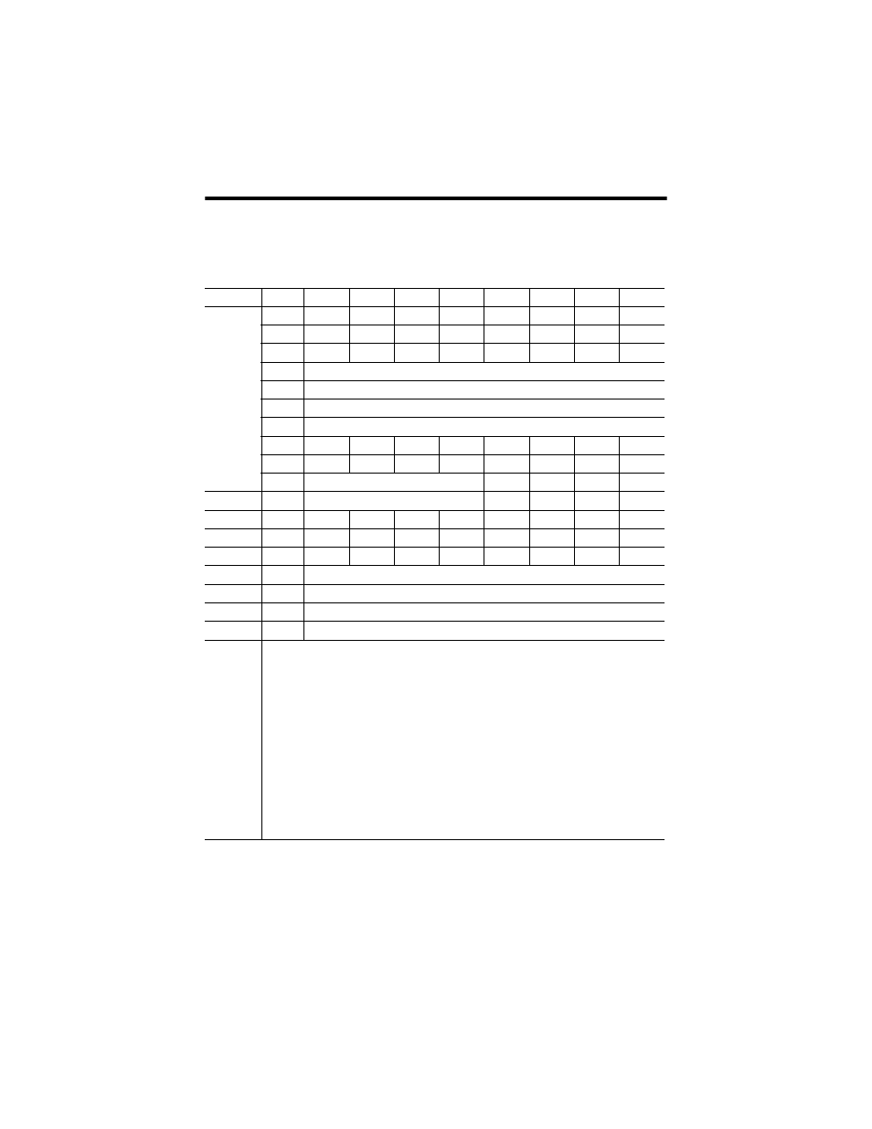
Word and bit definitions for the 1799-D16U16VAGL board are shown below.
Word and Bit Definitions for the 1799-D16U16VAGL Board
Produced
Byte
Bit 7
Bit 6
Bit 5
Bit 4
Bit 3
Bit 2
Bit 1
Bit 0
0
In8
In7
In6
In5
In4
In3
In2
In1
1
In16
In15
In14
In13
In12
In11
In10
In9
2
Rsvd
Logic En
Rsvd
Rsvd
OW1
OW0
OFLT 1
OFLT 0
3
Analog Input Channel 0 (LSB)
4
Analog Input Channel 0 (MSB)
5
Analog Input Channel 1 (LSB)
6
Analog Input Channel 1 (MSB)
7
ORI0
URI0
HHAI0
LLAI0
HAI0
LAI0
CMI0
STI0
8
ORI1
URI1
HHAI1
LLAI1
HAI1
LAI1
CMI1
STI1
9
Reserved
HCO0
LCO0
CMO0
STO0
10
Reserved
HCO1
LCO1
CMO1
STO1
Consumed Byte
Bit 7
Bit 6
Bit 5
Bit 4
Bit 3
Bit 2
Bit 1
Bit 0
0
O8
O7
O6
O5
O4
O3
O2
O1
1
O16
O15
O14
O13
O12
O11
O10
O9
2
Analog Output Channel 0 Data (LSB)
3
Analog Output Channel 0 Data (MSB)
4
Analog Output Channel 1 Data (LSB)
5
Analog Output Channel 1 Data (MSB)
Where: I = Digital input
O = Digital output
AI = Analog Input Channel (channel 0 = AI0; channel 1 = AI1)
AO = Analog Output Channel (channel 0 = AO0; channel 1 = AO1)
ST = Analog Input Channel Status (channel 0 = ST0; channel 1 = ST1) (0 = no error; 1 = fault)
CM = Calibration mode (0 = run; 1 = calibration mode)
LA = Low alarm (0 = no error; 1 = fault)
LLA = Low low alarm (0 = no error; 1 = fault)
HA = High alarm (0 = no error; 1 = fault)
HHA = High high alarm (0 = no error; 1 = fault)
UR = Underrange (0 = no error; 1 = fault)
OR = Overrange (0 = no error; 1 = fault)
LC = Low clamp (0 = no error; 1 = fault)
HC = High clamp (0 = no error; 1 = fault)
OW = Analog output open wire (OW0 = channel 0; OW1 = channel 1)
OFLT = Output fault on one or more outputs in a group (OFLT0 = group 0; OFLT1 = group 1)
Rsvd = Reserved