Auxiliary power specifications – Rockwell Automation 1799-D16U16BAGL 16 Input/16 Output Digital and 2 Input/2Output Analog User Manual
Page 11
16 Input/16 Output Digital and 2 Input/2 Output Analog Embedded I/O Boards 11
Publication 1799-IN011A-EN-P - February 2007
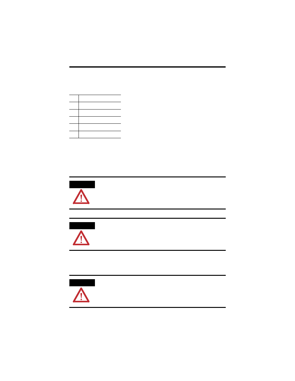
The DeviceNet wire insulation colors are shown below.
Auxiliary Power Specifications
The power source used to supply the auxiliary power to the outputs and analog circuitry must
meet the following:
These conditions requires that the board and power source be mounted in a suitable,
ultimate enclosure with proper spacings maintained.
P1 DeviceNet Connector
Pin
Insulation Colors
1
Black
2
Blue
3
Shield
4
White
5
Red
ATTENTION
To comply with the CE Low Voltage Directive (LVD), all connections to this equipment must be
powered from a source compliant with the following:
Safety Extra Low Voltage (SELV) or Protected Extra Low Voltage (PELV) with isolated outputs
limited to 200 volt-amperes in each ungrounded output line.
ATTENTION
To comply with UL restrictions, this equipment must be powered from a source compliant
with the following:
Class 2 or UL Listed /Recognized Power Supply with isolated outputs limited to
200 volt-amperes in each ungrounded output line. This condition requires that
the board and power source be mounted in a suitable ultimate enclosure with
proper spacings maintained.
ATTENTION
Do not wire more than 2 conductors on any single terminal.