Rockwell Automation 57C402 25-115V AC/DC Low Power Output Module User Manual
Page 13
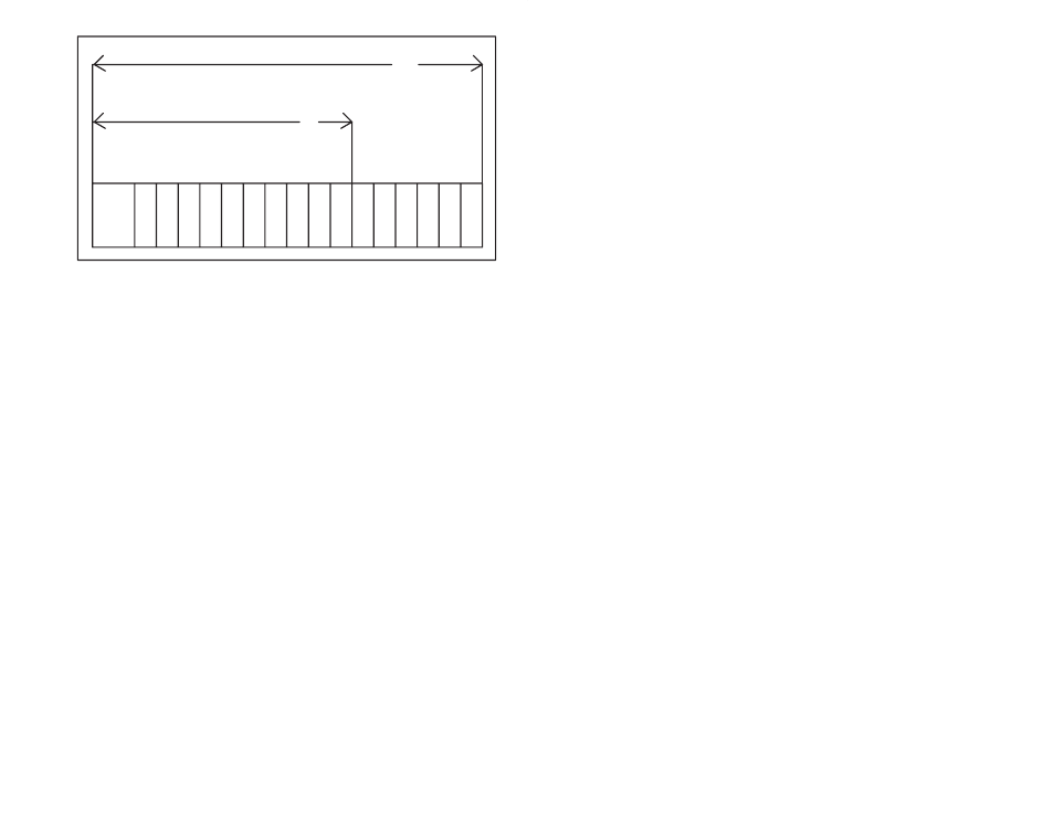
3Ć3
P/S
0
1
2
3
4
5
6
7
8
9 10 11 12 13 14 15
10
Typical 10 Slot Rack
16
Typical 16 Slot Rack
Figure 3.2 Ć Rack Slot Numbers
Step 6.
Attach the field terminal connector (M/N 57C370) to the
mating half on the module. Make certain that the
connector is the proper one for this module. Use a
screwdriver to secure the connector to the module.
Note that both the module and the terminal strip connector
are equipped with keys." These keys should be used to
prevent the wrong cable from being plugged into a
module in the event that the connector needs to be
removed for any reason and then reattached later.
At the time of installation, rotate the keys on the module
and the connector so that they can be connected together
securely. It is recommended that, for each module so
equipped, the keys on each successive module in the
rack be rotated one position to the right of the keys on the
preceding module.
If you use this method, the keys on a particular connector
will be positioned in such a way as to fit together only with
a specific module, and there will be little chance of the
wrong connector being attached to a module.
Step 7.
Turn on power to the system.
Step 8.
Verify the installation by connecting the programming
terminal to the system and running the ReSource
Software.
Stop all programs that may be running.
Use the I/O MONITOR function. If the module is in a local
rack, enter the module slot number and register (always
0).
If the module is in a remote rack, enter the slot number of
the master remote I/O module, remote I/O drop number
(also called the remote rack number), output module slot
number, and register (always 0).
One at a time, toggle each of the bits that have been wired
to output devices to verify that the installation has been
completed correctly.