Rockwell Automation 2755 High Performance VLD Scanner User Manual
Page 22
3–9
Installation Considerations
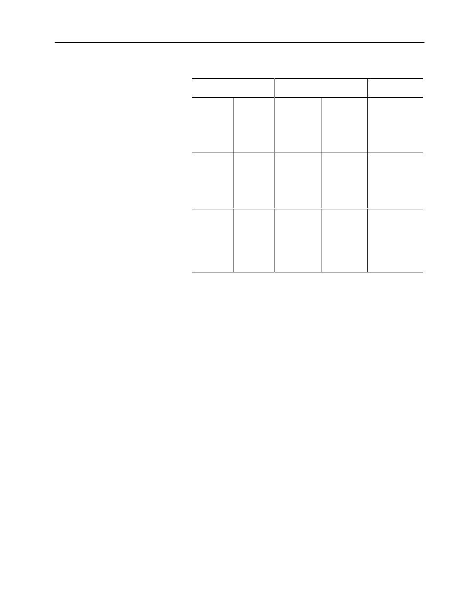
Table 3.B
LD8 Read Ranges ➀
Minimum Element Width ➁
Mils Millimeters
Read Range
Inches Centimeters
Catalog Number
4
5
7.5
10
13
20
30
.10
.15
.19
.25
.33
.51
.76
3.5 - 4.5
3.25 - 5.5
2.75 - 6.25
2.75 - 6.75
2.5 - 7.5
3.25 - 9.25
5.25 - 10.25
8.9 - 11.4
8.3 - 14.0
7.0 - 15.9
7.0 - 17.1
6.4 - 19.0
8.3 - 23.5
13.3 - 26.0
2755-LD8A1
2755-LD8A4
6
7.5
10
13
20
30
35
.15
.19
.25
.33
.51
.76
.89
7.0 - 11.75
7.0 - 12.5
6.75 - 14.0
6.75 - 16.0
6.75 - 20.0
6.0 - 20.0
5.5 - 20.0
17.8 - 29.8
17.8 - 31.8
17.1 - 35.6
17.1 - 40.6
17.1 - 50.8
15.2 - 50.8
14.0 - 50.8
2755-LD8B1
2755-LD8B4
9
10
13
20
30
35
40
50
.23
.25
.38
.51
.76
.89
1.02
1.27
14.5 - 19.5
14.25 - 22.75
13.75 - 26.75
12.75 - 36.0
11.0 - 41.75
10.0 - 44.5
10.0 - 47.5
10.0 - 50.0
36.8 - 49.5
36.2 - 57.8
34.9 - 67.9
32.4 - 91.4
27.9 - 106.0
25.4 - 113.0
25.4 - 120.6
25.4 - 127.0
2755-LD8C1
2755-LD8C4 ➂
➀ Read ranges are based on 4 character, Code 39 labels with a wide to narrow bar ratio
of 2.6 to 1 and a print contrast ratio of .75 or better. Read ranges will vary with bar
code symbol quality.
➁ For minimum element width, refer to ”Determining Apparent Minimum Element Width”
in Chapter 3.
➂ The glare that results from the laser striking reflective objects (conduit, metal
conveyors) may affect performance of the LD8C scanner when used at long ranges.
To minimize this effect, mask the area behind the symbol with a non-glossy material
(flat black paint) or reduce the scan line to avoid reflective objects. Reducing the scan
line will affect reading distances of the scanner.