Wiring the module, Working with connectors, See the figure that shows connectors – Rockwell Automation 1791ES-IB16 CompactBlock Guard I/O EtherNet/IP Safety Modules User Manual
Page 11
CompactBlock Guard I/O EtherNet/IP Safety Modules 11
Publication
1791ES-IN001C-EN-P - September 2009
Wiring the Module
Follow these guidelines when wiring the module:
•
1770-4.1
.
• Wire correctly after confirming the signal names of all terminals.
• Note that stranded wire should be processed with insulation-covered
ferrule (DIN 46228-4 standard compatible-type) at its ends before
using for connection.
• Tighten screws for the power connector correctly at 0.56…0.79 N•m
(5…7 lb•in).
• Tighten screws for the I/O connectors correctly at 0.5…0.56 N•m
(4.5…5 lb•in).
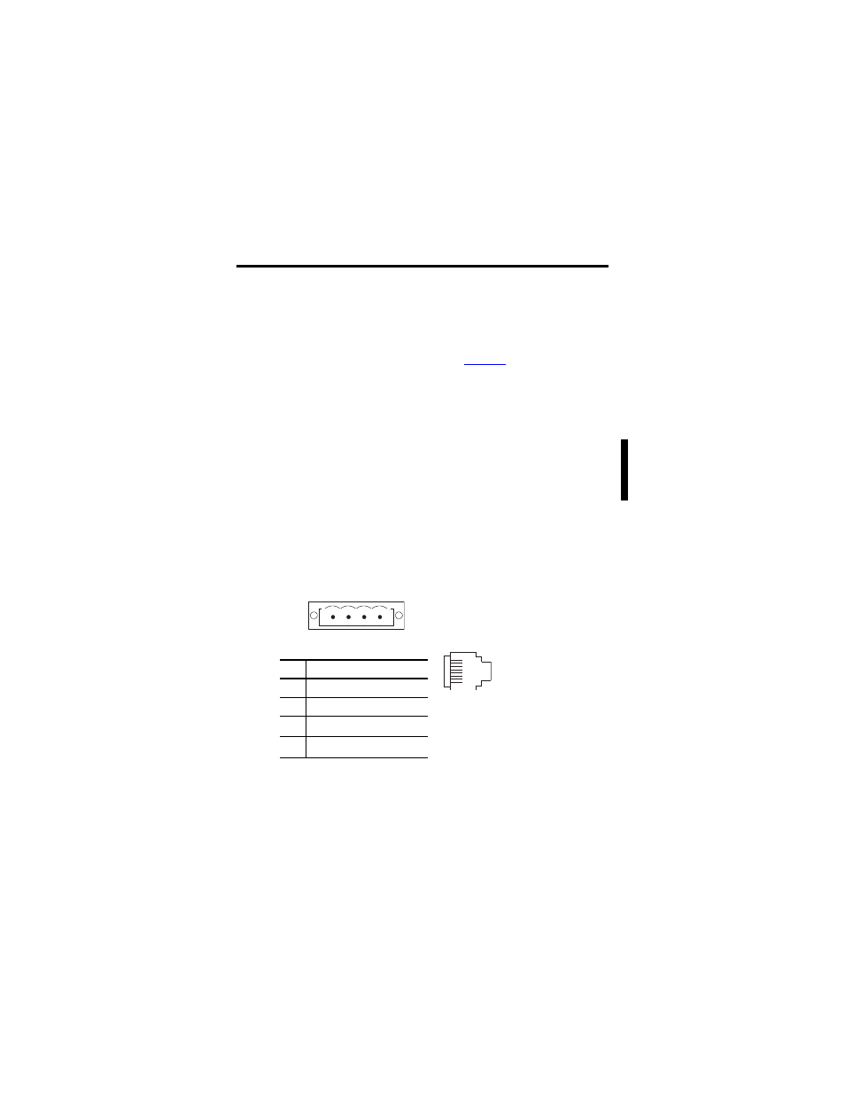
Working with Connectors
See the figure that shows connectors.
Power and EtherNet/IP Connectors
Power Configuration
Pin
Signal
1
Input +24V DC Power
2
Input Power Common
3
Output +24V DC Power
(1)
(1)
NC on 1791ES-IB16 modules.
4
Output Power Common
(1)
EtherNet/IP Connector
8 - No connection
7 - No connection
6 - Receive data minus
5 - No connection
4 - No connection
3 - Receive data plus
2 - Transmit data minus
1 - Transmit data plus
RJ45
8
1
44205
1
2
3
4