Install the controller, Dc in hsc dc out analog – Rockwell Automation 1769-L24ER-QB1B_QBFC1B_QBFC1B CompactLogix 5370 L2 Controllers Installation Instructions User Manual
Page 9
CompactLogix 5370 L2 Controllers 9
Rockwell Automation Publication 1769-IN090A-EN-P - April 2012
Install the Controller
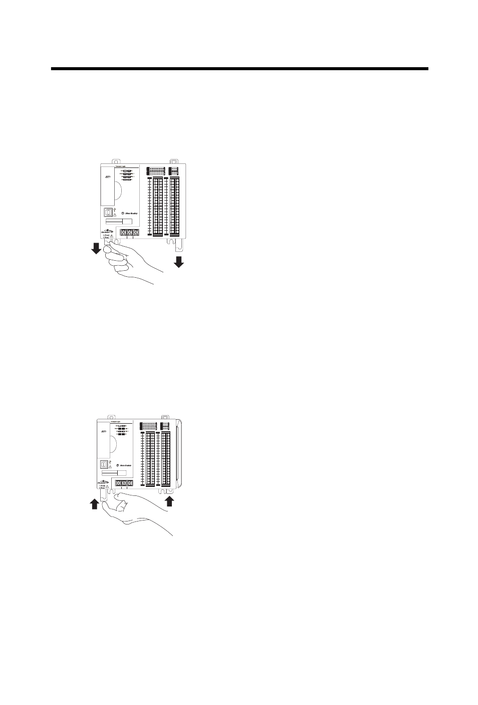
Complete these steps to install the controller.
1.
Pull the bottom locking tabs out.
2.
Hook the top of the controller on the DIN rail.
3.
Swing it downward until the controller is flush against the DIN rail and
push it down against the DIN rail.
4.
Push the controller against the DIN rail until the bottom DIN rail lock
on the back of the controller clicks, locking the controller in place.
5.
Push the locking tabs in.
0
1
2
3
4
5
6
7
8
9
10
11
12 13
14
15
0
1
2
3
4
5
6
7
8
9
10
A0
B0
Z0
A1
B1
Z1
0
2 FUSE
1
3
OK
11
12 13
14
15
HIGH SPEED
CO
U
N
T
E
R
IN
OUT
DC
INPUT
24VDC
SINK\
SOURCE
24VDC
SOURCE
OUTPUT
DC
+24VDC COM
FG
00
01
02
03
04
05
06
07
NC
+V
00
01
02
03
04
05
06
07
COM
0
COM
0
08
09
10
11
12
13
14
15
NC
+V
08
09
10
11
12
13
14
15
COM
1
COM
1
A0+
B0+
Z0+
A1+
B1+
Z1+
+V
OUT
1
OUT
0
COM COM
A0-
B0-
Z0-
A1-
B1-
Z1-
+V
0UT
3
V
in
0+
V
in
2+
V
OUT
0+
I
OUT
0+
V
OUT
1+
I
in
3+
V
in
1+
I
in
1+
I
in
1+
V
in
3+
CJC
-
CJC
+
V/I
in
1-
V/I
in
3-
V/I
in
0-
V/I
in
2-
I
in
0+
I
in
2+
OUT
2
COM
COM
DC IN
HSC
DC OUT
ANALOG
00:00:BC:2E:69:F6
L27ERM
QBFC1B
32256-M
32257-M
0
1
2
3
4
5
6
7
8
9
10
11
12 13
14
15
0
1
2
3
4
5
6
7
8
9
10
A0
B0
Z0
A1
B1
Z1
0
2 FUSE
1
3
OK
11
12 13
14
15
HIGH SPEED
C
OUNTER
IN
OUT
DC
INPUT
24VDC
SINK\
SOURCE
24VDC
SOURCE
OUTPUT
DC
+24VDC COM
FG
00
01
02
03
04
05
06
07
NC
+V
00
01
02
03
04
05
06
07
COM
0
COM
0
08
09
10
11
12
13
14
15
NC
+V
08
09
10
11
12
13
14
15
COM
1
COM
1
A0+
B0+
Z0+
A1+
B1+
Z1+
+V
OUT
1
OUT
0
COM COM
A0-
B0-
Z0-
A1-
B1-
Z1-
+V
0UT
3
V
in
0+
V
in
2+
V
OUT
0+
I
OUT
0+
V
OUT
1+
I
in
3+
V
in
1+
I
in
1+
I
in
1+
V
in
3+
CJC
-
CJC
+
V/I
in
1-
V/I
in
3-
V/I
in
0-
V/I
in
2-
I
in
0+
I
in
2+
OUT
2
COM
COM
DC IN
HSC
DC OUT
ANALOG
00:00:BC:2E:69:F6
L27ERM
QBFC1B