Wiring the embedded i/o modules, Dc input 24vdc sink\ source 24vdc source output dc, Dc in hsc dc out analog – Rockwell Automation 1769-L24ER-QB1B_QBFC1B_QBFC1B CompactLogix 5370 L2 Controllers Installation Instructions User Manual
Page 15
CompactLogix 5370 L2 Controllers 15
Rockwell Automation Publication 1769-IN090A-EN-P - April 2012
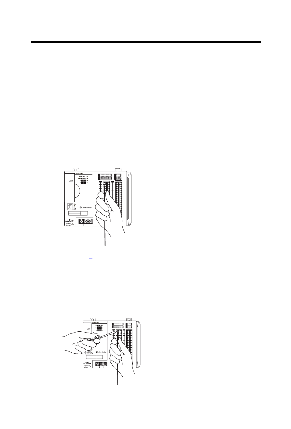
Wiring the Embedded I/O Modules
Complete these steps to wire the input and output points on the
CompactLogix 5370 L2 controller.
1.
Verify that the control system is not powered.
2.
Strip 10 mm (0.39 in.) insulation from the end of the wire.
3.
Push the wire into the connector hole until it is securely in place.
If your wire is too thin to push into the connector hole for secure
placement, we recommend that you connect the wire to a ferrule and
then insert it into the connector hole.
4.
Repeat step
for all embedded I/O wires needed in your application.
To remove a wire from the removable connector, complete these steps.
1.
Verify that the control system is not powered.
2.
Use a small screwdriver to push on the spring release clip and pull the
wire out.
L27ERM
0
1
2
3
4
5
6
7
8
9
10
11
12 13
14
15
0
1
2
3
4
5
6
7
8
9
10
A0
B0
Z0
A1
B1
Z1
0
2 FUSE
1
3
OK
11
12 13
14
15
HIGH SPEED
C
OUNTER
IN
OUT
DC
INPUT
24VDC
SINK\
SOURCE
24VDC
SOURCE
OUTPUT
DC
+24VDC COM
FG
00
01
02
03
04
05
06
07
NC
+V
00
01
02
03
04
05
06
07
COM
0
COM
0
08
09
10
11
12
13
14
15
NC
+V
08
09
10
11
12
13
14
15
COM
1
COM
1
A0+
B0+
Z0+
A1+
B1+
Z1+
+V
OUT
1
OUT
0
COM COM
A0-
B0-
Z0-
A1-
B1-
Z1-
+V
0UT
3
V
in
0+
V
in
2+
V
OUT
0+
I
OUT
0+
V
OUT
1+
I
in
3+
V
in
1+
I
in
1+
I
in
1+
V
in
3+
CJC
-
CJC
+
V/I
in
1-
V/I
in
3-
V/I
in
0-
V/I
in
2-
I
in
0+
I
in
2+
OUT
2
COM
COM
DC IN
HSC
DC OUT
ANALOG
QBFC1B