Install the module – Rockwell Automation 1734-IT2I, Series C Point I/O RTD and Isolated Thermocouple Input Module Installation Instructions User Manual
Page 9
POINT I/O™ RTD and Isolated Thermocouple Input Modules 9
Publication 1734-IN011H-EN-E - February 2014
Install the Module
The module can be installed before or after base installation. Make sure that the mounting
base is correctly keyed before installing the module into the mounting base. In addition,
make sure the mounting base locking screw is positioned horizontal referenced to the base.
ATTENTION: When you insert or remove the module while backplane power is
on, an electrical arc can occur. This could cause an explosion in hazardous
location installations.
Be sure that power is removed or the area is nonhazardous before proceeding.
Repeated electrical arcing causes excessive wear to contacts on both the
module and its mating connector. Worn contacts may create electrical
resistance that can affect module operation.
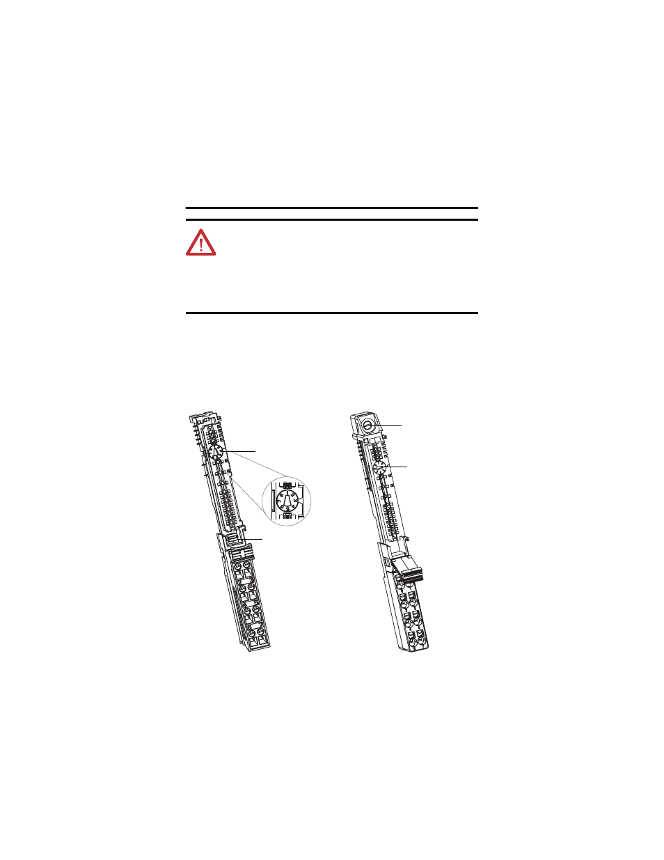
Turn the keyswitch to
align the number with
the notch. Notch
position 3 is shown.
Be sure the DIN-rail
locking screw is in the
horizontal position.
1734-TB Base
44229
Turn the keyswitch
to align the number
with the notch.
Notch position 1 is
shown.
Be sure the DIN-rail
locking screw is in the
horizontal position.
1734-TOP Base
44228