Communicate with the module – Rockwell Automation 1734-IT2I, Series C Point I/O RTD and Isolated Thermocouple Input Module Installation Instructions User Manual
Page 15
POINT I/O™ RTD and Isolated Thermocouple Input Modules 15
Publication 1734-IN011H-EN-E - February 2014
Communicate with the Module
POINT I/O modules send (produce) and receive (consume) I/O data (messages). You
map this data into the processor’s memory.
The 1734-IR2 and 1734-IR2E modules produce 6 bytes of input data (scanner Rx) and
fault status data. The 1734-IT2I module produces 8 bytes of input data (scanner Rx) and
fault status data. The modules do not consume I/O data (scanner Tx).
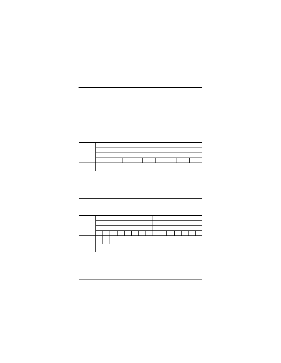
Default Data Map for RTD Input Module – 1734-IR2, 1734-IR2E
Message size: 6 Bytes
Produces
(scanner Rx)
Input channel 0 – high byte
Input channel 0 – low byte
Input channel 1 – high byte
Input channel 1 – low byte
Status byte for channel 1
Status byte for channel 0
OR
UR
HHA LLA HA LA
CM CF
OR
UR
HHA LLA HA LA
CM CF
Consumes
(scanner Tx)
No consumed data
Where:
OR = Overrange; 0 = No error, 1 = Fault
UR = Underrange; 0 = No error, 1 = Fault
HHA = High/High Alarm; 0 = No error, 1 = Fault
LLA = Low/Low Alarm; 0 = No error, 1 = Fault
HA = High Alarm; 0 = No error, 1 = Fault
LA = Low Alarm; 0 = No error, 1 = Fault
CM = Calibration Mode; 0 = Normal, 1 = Calibration mode
CF = Channel Fault Status; 0 = No error, 1 = Fault
Default Data Map for Isolated Thermocouple Input Module – 1734-IT2I
Message size: 8 Bytes
Produces
(scanner Rx)
Input channel 0 – high byte
Input channel 0 – low byte
Input channel 1 – high byte
Input channel 1 – low byte
Status byte for channel 1
Status byte for channel 0
OR
UR
HHA LLA HA
LA
CM CF
OR
UR
HHA LLA HA
LA
CM
OR
UR
Cold Junction Temperature
(Selectable: channel 0, channel 1, or average of both channels 0 and 1)
Consumes
(scanner Tx)
No consumed data
Where:
OR = Overrange; 0 = No error, 1 = Fault
UR = Underrange; 0 = No error, 1 = Fault
HHA = High/High Alarm; 0 = No error, 1 = Fault
LLA = Low/Low Alarm; 0 = No error, 1 = Fault
HA = High Alarm; 0 = No error, 1 = Fault
LA = Low Alarm; 0 = No error, 1 = Fault
CM = Calibration Mode; 0 = Normal, 1 = Calibration mode
CF = Channel Fault Status; 0 = No error, 1 = Fault