I/o memory mapping – Rockwell Automation 1790-TXXXX CompactBlock LDX I/O Profibus Analog, RTD and Thermocouple User Manual
Page 17
17
Publication 1790-IN010B-EN-P - April 2003
I/O Memory Mapping
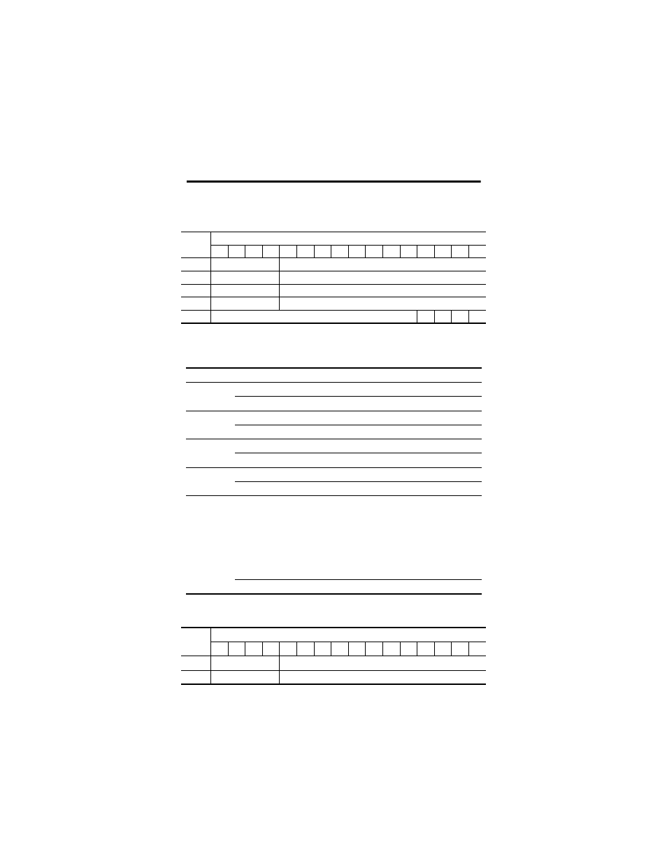
1790P-TN4C0 Analog Input Module Input Data File
Word/Bit Descriptions for 1790P-TN4C0 Analog Input Module
1790P-TN0C2 Analog Output Module Output Data File
Word
Bit Position
15
14
13
12
11
10
9
8
7
6
5
4
3
2
1
0
0
Not Used
Analog Input Data Channel 0
1
Not Used
Analog Input Data Channel 1
2
Not Used
Analog Input Data Channel 2
3
Not Used
Analog Input Data Channel 3
4
Not Used
S3
S2
S1
S0
Word
Decimal Bit
Description
Read Word 0
Bits 00-11
Channel 0 input data
Bits 12-15
Not used: Set to 0
Read Word 1
Bits 00-11
Channel 1 input data
Bits 12-15
Not used: Set to 0
Read Word 2
Bits 00-11
Channel 2 input data
Bits 12-15
Not used: Set to 0
Read Word 3
Bits 00-11
Channel 3 input data
Bits 12-15
Not used: Set to 0
Read Word 4
Bits 00-03
Status bits for individual channels - Bit 00 corresponds to
input channel 0, bit 01 corresponds to input channel 1 and
so on.
When set (1) indicates:
• No field power
• Open wire (4-20mA current input only)
• Under range (4-20mA current input only)
• Recoverable module fault (whole channel to be set)
• Unrecoverable module fault (whole channel to be set)
Bits 04-15
Not used: Set to 0
Word
Bit Position
15
14
13
12
11
10
9
8
7
6
5
4
3
2
1
0
0
Not Used
Analog Output Data Channel 0
1
Not Used
Analog Output Data Channel 1