Rockwell Automation 1771-DCM USER MANUAL 1771-DCM User Manual
Page 25
Programming the 1771-DCM
Chapter 6
6Ć4
First (Starting) Module Group Number (Switch Bank 1, Switches 7 and
8)
The slot number will always be zero for block transfer only.
Equivalent rack size for discrete data transfer only (Switch Bank 0,
Switches 7 and 8). The equivalent rack size for block transfer mode is
fixed at 1/4 rack.
Discrete Data Transfer
The supervisory processor transfers discrete data to and from the
1771–DCM automatically via its I/O scan. You do not program these
transfers.
To transfer discrete data words to and from the 1771–DCM, you must use
I/O image table addresses in the supervisory processor’s ladder program
starting with the addresses (RGS) to which you configured your
1771–DCM. Use the number of image table words equal to the
equivalent I/O rack size that you set for the 1771–DCM.
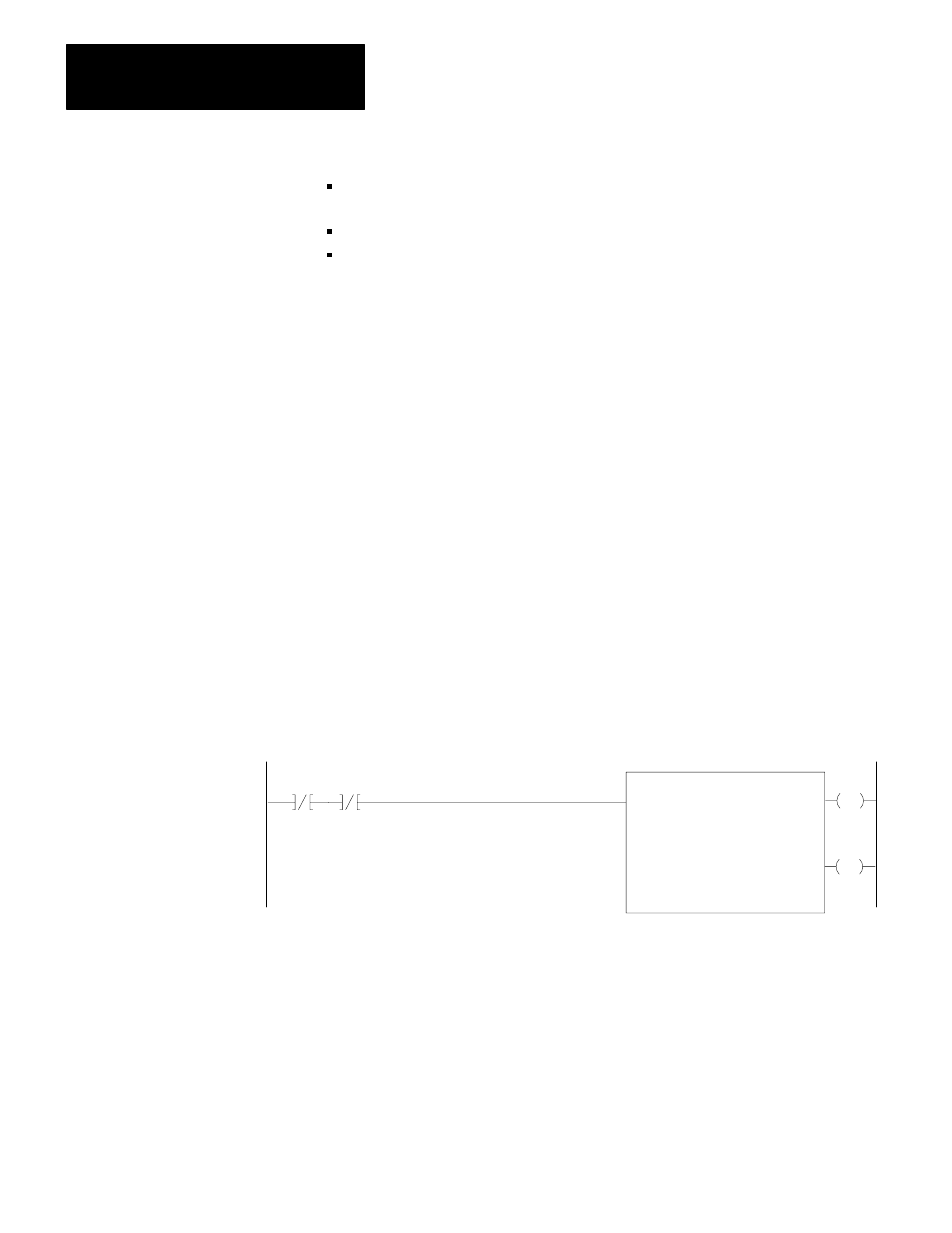
The ladder program of your supervisory processor must move discrete
data, read from the 1771–DCM, from input image table words to a storage
location (Figure 6.3).
Figure 6.3
Supervisory Processor Programming Example for Discrete Data Transfer (PLC-2/30)
EN
FILE TO FILE MOVE
Counter Address:
Position:
File Length:
File A:
0041
001
008
0120-0127
File R:
0700-0707
Rate per Scan:
008
0041
17
DN
0041
15
15
041
10
120
Buffer File
Data Valid Bit
FFM Done Bit
Your ladder program must place data into output image table words for
transfer to the 1771–DCM. Avoid placing data in the first word because
the 1771–DCM inserts status in this word. We leave this ladder logic to
you because your application and processor’s set of instructions determine
how you would do this.