Rockwell Automation 1771-OBN DC (10-30V) Output Module Installation Instructions User Manual
Page 9
DC (10-30V) Output Module
9
Publication 1771ĆIN034B-EN-P - August 2002
!
ATTENTION
Observe proper polarity with dc power
connections. Reverse polarity, or application of ac
voltage could damage the module.
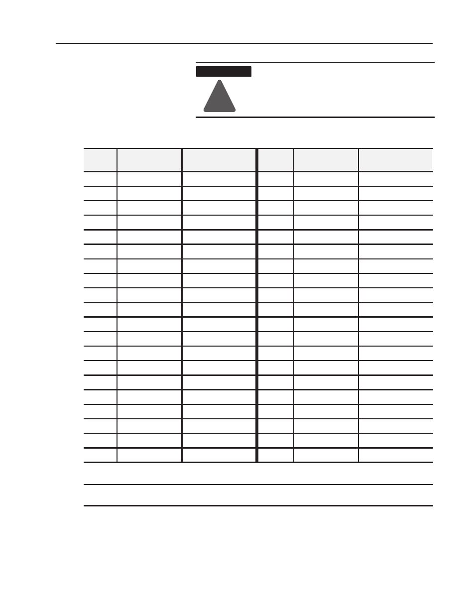
Table A
Module Output Terminal Assignments
Terminal
Number
Output Assignment
I/O program address
Terminal
Number
Output Assignment
I/O program address
01
1
10 to 30V dc
Ć
21
1
10 to 30V dc
Ć
02
Output 00
0RG00
22
Output 00
0RG00
03
Output 01
0RG01
23
Output 01
0RG01
04
Output 02
0RG02
24
Output 02
0RG02
05
Output 03
0RG03
25
Output 03
0RG03
06
Output 04
0RG04
26
Output 04
0RG04
07
Output 05
0RG05
27
Output 05
0RG05
08
Output 06
0RG06
28
Output 06
0RG06
09
Output 07
0RG07
29
Output 07
0RG07
10
Common 0
Ć
30
Common 2
Ć
11
1
10 to 30V dc
Ć
31
1
10 to 30V dc
Ć
12
Output 10
0RG10
32
Output 10
0RG10
13
Output 11
0RG11
33
Output 11
0RG11
14
Output 12
0RG12
34
Output 12
0RG12
15
Output 13
0RG13
35
Output 13
0RG13
16
Output 14
0RG14
36
Output 14
0RG14
17
Output 15
0RG15
37
Output 15
0RG15
18
Output 16
0RG16
38
Output 16
0RG16
19
Output 17
0RG17
39
Output 17
0RG17
20
Common 1
Ć
40
Common 3
Ć
Where:
R = rack number (1, 2, 3, etc.)
G = I/O group (0 Ć 7)
1
You can connect a different power supply to each 10 to 30V dc terminal. They are not connected internally. Connect each common (0, 1, 2, 3) to the corresponding supply.
Commons are not internally connected.
Ifmultiple power sources are used, do not exceed the specified isolation voltage.