Rockwell Automation 1771-OBN DC (10-30V) Output Module Installation Instructions User Manual
Page 6
DC (10-30V) Output Module
6
Publication 1771ĆIN034B-EN-P - August 2002
!
ATTENTION
Remove power from the 1771 I/O chassis
backplane before you install the module. Failure
to remove power from the backplane could cause:
•
module damage
•
degradation of performance
•
injury or equipment damage due to possible
unexpected operation
!
WARNING
When you insert or remove the module with field
power applied, or connect or disconnect the field
wiring arm with field side power applied, an
electrical arc can occur. This could cause an
explosion in hazardous location installations.Be
sure that power is removed or the area is
nonhazardous before proceeding.
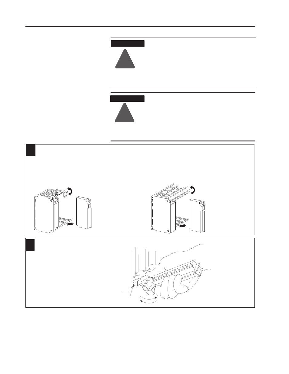
Place the module in the card guides on the top and bottom ofthe chassis
that guide the module into position.
Important:
Apply firm even pressure on the module to seat it into its
backplane connector.
1
1771ĆA1B, ĆA2B, ĆA3B, ĆA4B I/O chassis
Snap the chassis latch over the
top ofthe module to secure it.
Swing the chassis locking bar
down into place to secure the
modules. Make sure the locking
pins engage.
1771ĆA1B, ĆA2B, ĆA4B Series B I/O chassis
Attach the wiring arm (1771ĆWN) to the horizontal bar at the
bottom ofthe I/O chassis.
The wiring arm pivots upward and connects with the
module so you can install or remove the module without
disconnecting the wires.
2
1771ĆWN
install
remove
horizontal bar
The 1771–OBN module is a modular component of the 1771 I/O
system requiring a properly installed system chassis. Refer to
publication 1771–IN075 for detailed information on acceptable
chassis, proper installation and grounding requirements. Limit the
maximum adjacent slot power dissipation to 10W maximum.
Install the Module and
Field Wiring Arm