Rockwell Automation 1771-OBN DC (10-30V) Output Module Installation Instructions User Manual
Page 8
DC (10-30V) Output Module
8
Publication 1771ĆIN034B-EN-P - August 2002
I/O Module Groups
Each module condenses 2 full module groups (32 outputs) into each
I/O chassis slot. For example:
Module group 1 = outputs 00 through 17
Module group 2 = outputs 00 through 17 (module group 2
represents the second set of outputs).
Terminals 1 through 20 represent module group 1. Terminals 21
through 40 represent module group 2. Terminals 10, 20, 30 and 40
are DC common and terminals 1, 11, 21 and 31 are DC power.
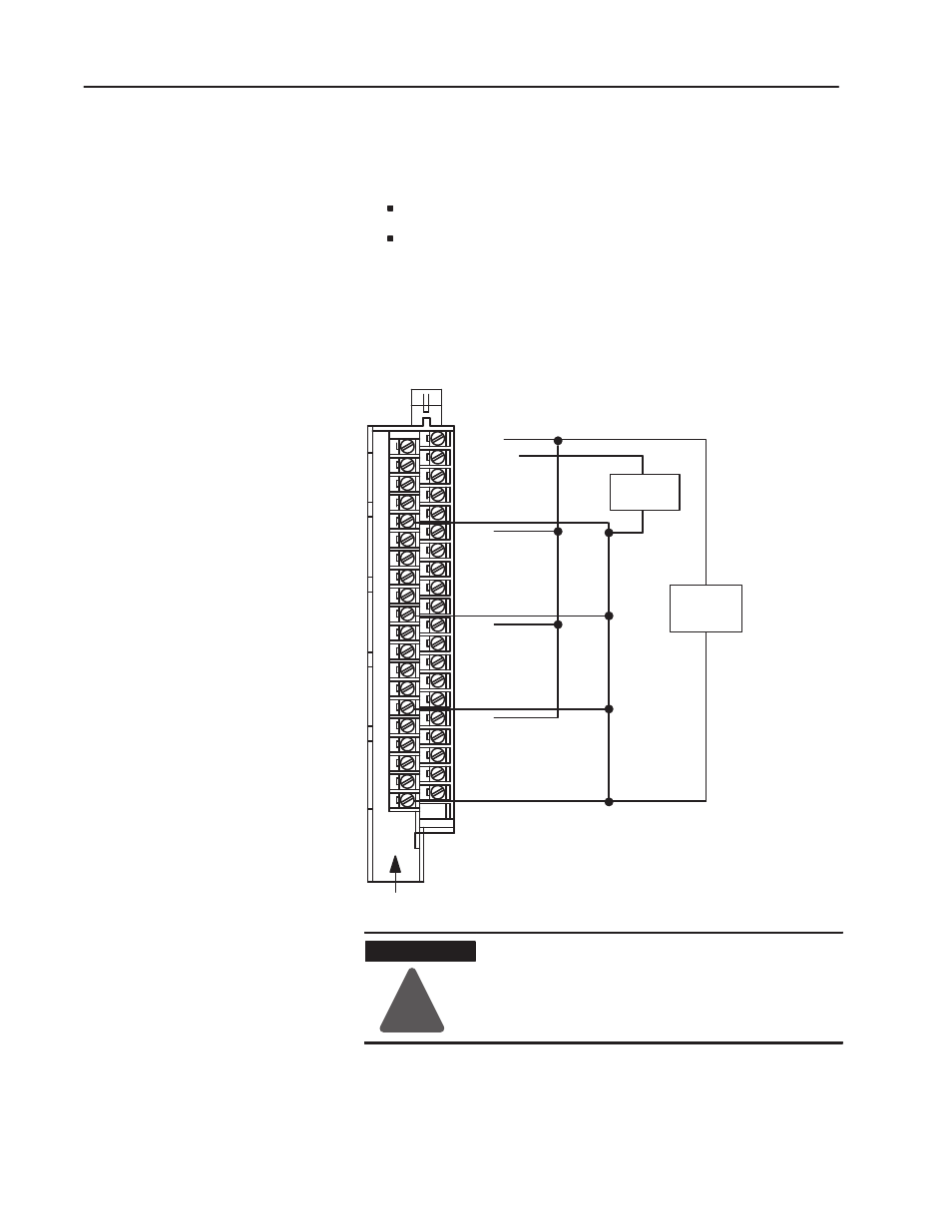
Connection Diagram for the 1771-OBN DC Output Module
Output 0
Output 2
Output 4
Output 6
Common 0
Output 10
Output 12
Output 14
Output 16
Common 1
Output 0
Output 2
Output 4
Output 6
Common 2
Output 10
Output 12
Output 14
Output 16
Common 3
+ dc
Output 1
Output 3
Output 5
Output 7
+ dc
Output 11
Output 13
Output 15
Output 17
+ dc
Output 1
Output 3
Output 5
Output 7
+ dc
Output 11
Output 13
Output 15
Output 17
+
-
dc
Supply
dc Output
Device
-
+
Note: Terminals on the left are
even numbered (2 thru 40) , and
terminals on the right are odd
numbered (1 thru 39).
2
4
6
8
10
12
14
16
18
20
22
24
26
28
30
32
34
36
38
40
Actual wiring runs in this direction.
11850ĆI
Ifmultiple power supplies are used, do not exceed the specified isolation voltage.
!
ATTENTION
Miswiring or shorting the output terminals will
cause permanent damage to this module.