Key the backplane connector, Calculate power supply requirements – Rockwell Automation 1771-OBN DC (10-30V) Output Module Installation Instructions User Manual
Page 5
DC (10-30V) Output Module
5
Publication 1771ĆIN034B-EN-P - August 2002
The controller or I/O chassis power supply, connected through the
backplane of the I/O chassis, powers the logic circuitry of the output
modules. The maximum current drawn from this supply is 330mA.
To calculate the requirements for the backplane power supply, add
330mA to the power requirements of all other modules in the I/O
chassis. Calculating the requirements will prevent an overload to the
chassis backplane and/or backplane power supply.
Key the Backplane
Connector
Place your module in any slot in the chassis
except the leftmost slot which is reserved
for processors or adapters.
Observe the following
precautions when inserting or
removing keys:
•
insert or remove keys with
your fingers
•
make sure that key placement
is correct
Incorrect keying or the use of a
tool can result in damage to the
backplane connector and
possible system faults.
!
ATTENTION
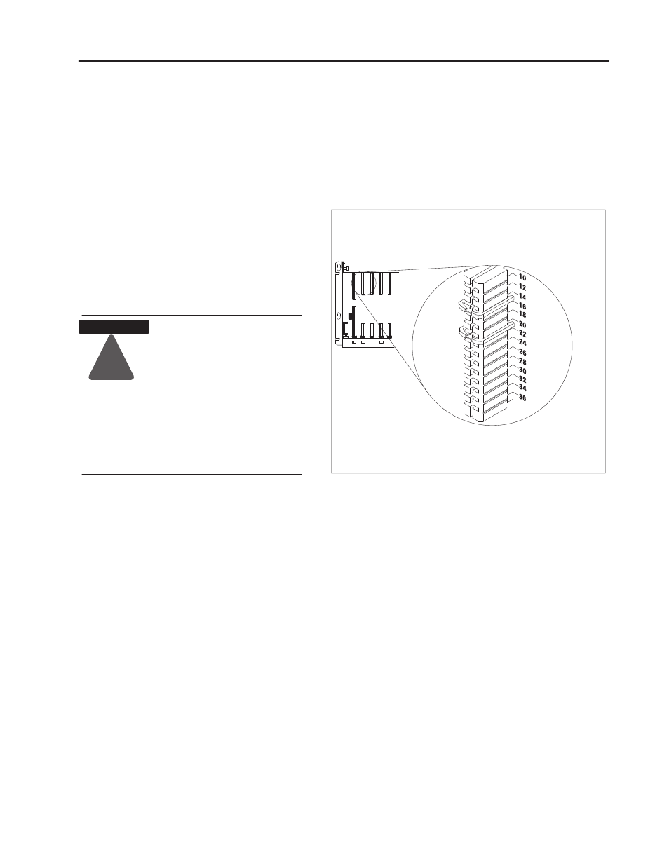
Position the keying bands in the backplane connectors to correspond to
the key slots on the module.
Place the keying bands:
- between 14 and 16
- between 20 and 22
You can change the position ofthese bands if
subsequent system design and rewiring makes
insertion ofa different type ofmodule necessary.
Upper
Connector
11022ĆI
I/O chassis
Calculate Power Supply
Requirements