Outputs – Rockwell Automation 1746-HSCE High-Speed Counter Module Installation Instructions User Manual
Page 14
14 High-Speed Counter Module
Publication 1746-IN011C-EN-P - April 2005
Outputs
The module features four physical outputs. They can be controlled by the module
when certain counter conditions are met, or they can be controlled from the user
program (refer to the High-Speed Counter Module User Manual, publication
1746-6.5 for M0:e.0 information).
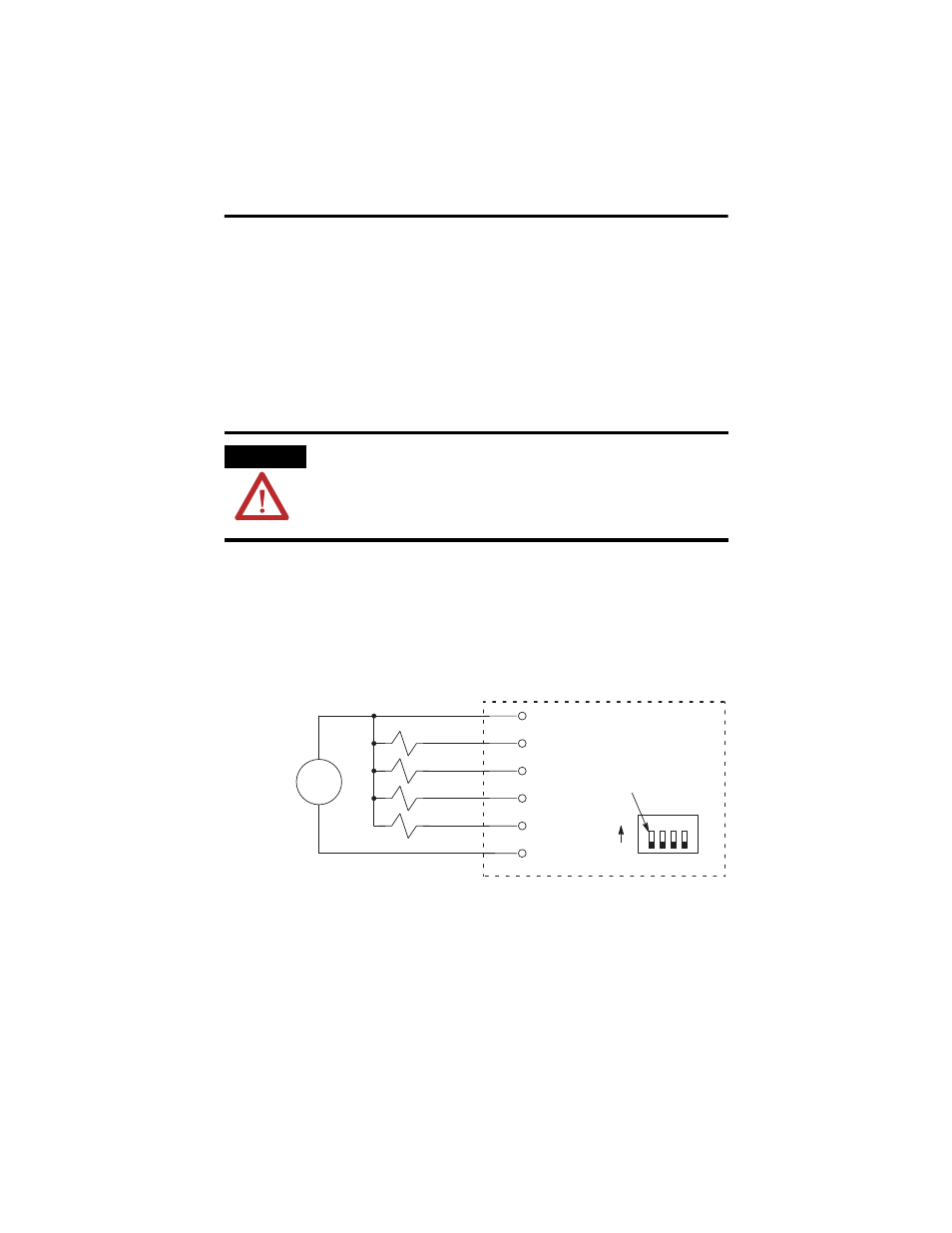
The outputs are bipolar transistors connected in a sinking (open collector sinking)
configuration. When the output is energized, it sinks the current.
You can select an output voltage range of 4.5 to 10V dc or 10 to 30V dc. Refer to
page 21 for the maximum current specifications for each voltage range. Dip switch
SW2, located on the PC board, is used to select the voltage range. See pages 6 and
8 for switch SW2 location and settings.
The figure below indicates wiring connections for four 24V dc outputs. All switches
of SW2 are OFF for this output voltage.
The outputs are not electrically isolated from each other. (They are referenced to
the same output common terminal.) However, outputs are isolated from the rest of
the circuitry to a level of 1500 volts.
ATTENTION
Do not use incandescent lamps as output indicators. The high
peak inrush current required to heat the filament can damage
the module’s output circuits. Use LED indicators that satisfy the
output circuit ratings, such as Allen-Bradley 800A and 800T LED
indicators.
+
-
1 2 3 4
User Supplied
24V dc
wiring terminals
DC COM
All switches OFF
ON
OFF
Dip Switch SW2
HSCE module
OUT 3
OUT 2
OUT 1
OUT 0
VDC