Rockwell Automation 1771-IFF/A INSTL.INSTR FAST ANALOG INPUT User Manual
Page 15
Publication 1771-IN046B-EN-P - December 2003
Fast Analog Input Module 15
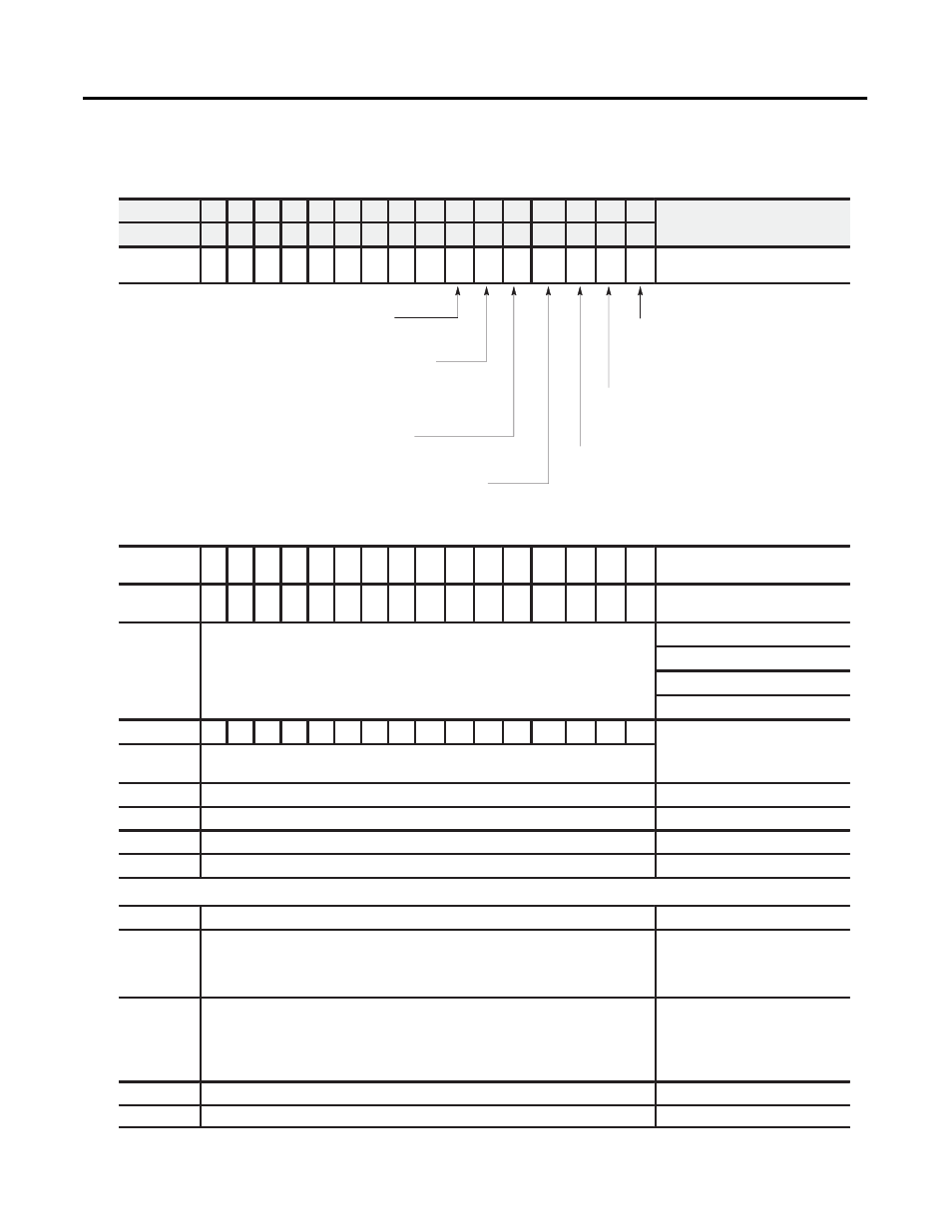
Use the following table to read data from your input module.
Dec. Bits
15
14
13
12
11
10
09
08
07
06
05
04
03
02
01
00
Octal Bits
17
16
15
14
13
12
11
10
07
06
05
04
03
02
01
00
Word 1
HF
EE
CS
RTS
IS
OR
PU
Diagnostics
Hardware fault -
(HF) When this bit is set, the
dc/dc converter fuse has blown. Digital logic will
continue to operate.
EEPROM status bit -
(EE) This bit is set if an error occurs
saving calibration data to nonvolatile memory . If this bit is
set at powerup, the data from the EEPROM did not pass the
checksum and no calibration values are used.
Calibration status bit -
(CS) When calibrating the module,
this bit will be cleared if the calibration was successful. If the
bit is set, an incorrect voltage/current was applied, or
offset and gain calibrations were attempted simultaneously
.
Real time sample fault bit - (R TS) This bit is set if the module
is configured for R TS and a block transfer read has not occurred
within the user±programmed period.
Power up bit -
(PU) Used by the
module to tell the processor that it is
alive but not yet configured. It is a key
element in the application program.
Out of range bit -
(OR) This bit is sent
to tell the processor that one or more
channels are either over or under range.
Invalid scaling bit - (IS) This bit reports
that the scaling is somehow invalid. Usually
,
both values are equal or minimum is greater
than maximum when this bit comes on. Can
also be an invalid filter value.
2
16
15
14
13
12
11
10
9
8
7
6
5
4
3
2
1
Data underrange for channels
1-16
3
16
15
14
13
12
11
10
9
8
7
6
5
4
3
2
1
Data overrange for channels
1-16
Underrange bits for each channel Bit 00 for channel 1 bit 01 for channel 2 etc
1 to 5V dc, 4 to 20mA (default)
Underrange b t s for each channel. Bit 00 for channel 1, bit 01 for channel 2, etc.
These bits are set (1) at approximately the input range limits shown on the right.
0 to 5V dc, 0 to 20mA
Overrange bits for each channel. Bit 00 for channel 1, bit 01 for channel 2, etc.
-5 to +5V dc, -20 to +20mA
-10 to +10V dc, 0 to 10V dc
4
16
15
14
13
12
11
10
9
8
7
6
5
4
3
2
1
Polarity bits - Set when input is less than zero. Bit 00 for channel 1, bit 01 for
channel 2, etc.
Data polarity for channels 1-16
5
Channel 1 Input
Channel 1 Input
6
Channel 2 Input
Channel 2 Input
7
Channel 3 Input
Channel 3 Input
8
Channel 4 Input
Channel 4 Input
20
Channel 16 Input
Channel 16 Input
21
Offset calibration results bits - Each bit represents a channel. After a
calibration BTW has been sent, the module confirms calibration by echoing back
the channels that were calibrated during the offset calibration BTW . In
dif ferential mode, channels 09 thru 16 are zero.
Of fset Calibration Results
22
Gain calibration results bits
- Each bit represents a channel. After a calibration
BTW has been sent, the module confirms calibration by echoing back the
channels that were calibrated during the gain calibration BTW. In dif ferential
mode, channels 09 thru 16 are zero.
Gain Calibration Results
23
binary, 1ms resolution
Time Stamp
24
10 ms resolution
Scan time
Description
These bits are set (1) at approximately the input range limits shown on the right.
⇓ ⇓ ⇓ ⇓