Rockwell Automation 1771-IFF/A INSTL.INSTR FAST ANALOG INPUT User Manual
Page 12
Publication 1771-IN046B-EN-P - December 2003
12 Fast Analog Input Module
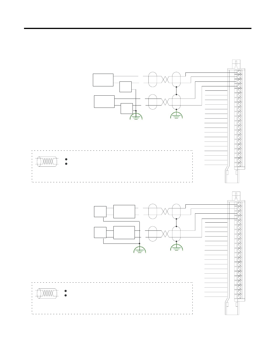
differential wiring
Functional Ground
– Unused channels must have their + and
- inputs jumpered together and tied to
module common to reduce noise.
1771-WG
Field W iring Arm
Note:
The 1771-IFF module does not supply loop power for the input device.
The user must supply loop power for loop-powered input devices.
+
–
Channel 1+
Channel 1-
Channel 2+
Channel 2-
Channel 3+
Channel 3-
Channel 4+
Channel 4-
Channel 5+
Channel 5-
Channel 6+
Channel 6-
Channel 7+
Channel 7-
Channel 8+
Channel 8-
Module Common
Not used
Not used
Not used
Module Common
1
2
3
4
5
6
7
8
9
10
11
12
13
14
15
16
17
18
19
20
21
Configuring the module for differential inputs does not provide isolation.
–
Tie power supply grounds together to
minimize ground loops.
Note: Refer to transmitter manufacturers
specifications for power supply connections.
+
Power
Supply
2-Wire
Transmitter
Power
Supply
2-Wire
Transmitter
–
The sensor cable must be shielded. The shield must:
extend the length of the cable, but be connected only at the 1771 I/O chassis
extend up to the point of termination
Important:
The shield should extend to the termination point, exposing just enough
cable to adequately terminate the inner conductors. Use heat shrink or
another suitable insulation where the wire exits the cable jacket.
– Unused channels must have their + and
- inputs jumpered together and tied to
module common to reduce noise.
1771-WG
Field Wiring Arm
Note:
The 1771-IFF module does not supply loop power for the input device.
The user must supply loop power for loop-powered input devices.
+
–
Channel 1+
Channel 1-
Channel 2+
Channel 2-
Channel 3+
Channel 3-
Channel 4+
Channel 4-
Channel 5+
Channel 5-
Channel 6+
Channel 6-
Channel 7+
Channel 7-
Channel 8+
Channel 8-
Module Common
Not used
Not used
Not used
Module Common
1
2
3
4
5
6
7
8
9
10
11
12
13
14
15
16
17
18
19
20
21
Configuring the module for differential inputs does not provide isolation.
–
Tie power supply grounds together to
minimize ground loops.
Note: Refer to transmitter manufacturers
specifications for power supply connections.
+
–
The sensor cable must be shielded. The shield must:
extend the length of the cable, but be connected only at the 1771 I/O chassis
extend up to the point of termination
Important:
The shield should extend to the termination point, exposing just enough
cable to adequately terminate the inner conductors. Use heat shrink or
another suitable insulation where the wire exits the cable jacket.
Power
Supply
4-Wire
Transmitter
Power
Supply
4-Wire
Transmitter
Connection Diagram for 8 Differential Inputs and Two-Wire Transmitters
Connection Diagram for 8 Differential Inputs and Four-Wire Transmitters
Functional Ground