Rockwell Automation 1756-CNB ControlLogix ControlNet Bridge Module Installation Instructions User Manual
Page 19
19
Publication 1756-IN571B-EN-P - April 2001
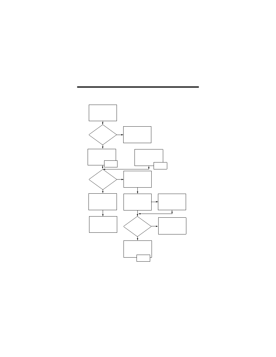
3. Apply power to the module and check module status. Use the
following flowchart as a guide.
Turn the chassis
power supply on.
Module
status
indicator
red?
See the
troubleshooting
table on page 23.
Module performs a
power-on self-test
initialization.
No
Yes
INIT
No
Yes
Module
status
indicator
red?
INIT has failed, and
the module displays
an error message
(see pages 23 - 26).
Replace the module.
OR
WAIT
RM
Modules are in a
redundant control
chassis pair.
Initialization is
complete. The
status indicator
blinks green.
Channel A and B
indicators alternately
flash.
Channel A and B
indicators display the
network condition as
listed on page 26.
Module
status
displays
OK?
No
See the
troubleshooting table
beginning on page 23.
Yes
Module is functional
and operating.
OK
A#xx