Interpret status indicators, Troubleshooting, Interpret status indicators troubleshooting – Rockwell Automation 1771-IXHR INSTL INSTR HI RES TC/MV INPUT User Manual
Page 9
High Resolution Thermocouple/Millivolt Input Module
9
Publication 1771-5.66 – October 1998
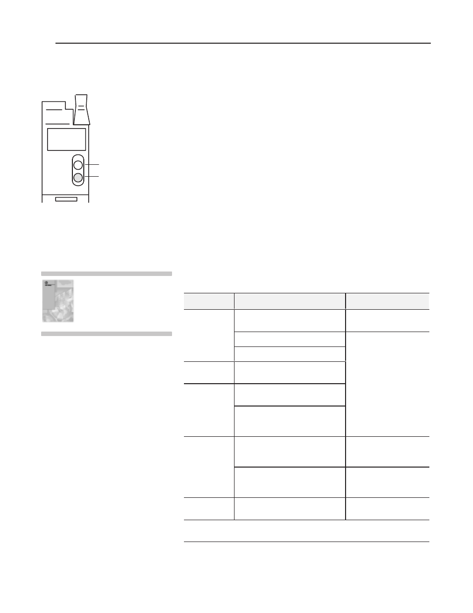
The front panel of the input module contains a green RUN indicator
and a red FAULT indicator. At power-up, the module momentarily
turns on both indicators as a lamp test, then checks for:
•
correct RAM operation
•
EPROM operation
•
EEPROM operation
•
a valid write block transfer with configuration data
If there is no fault, the red indicator turns off.
The green indicator comes on when the module is powered. It will
flash until the module is programmed. If a fault is found initially or
occurs later, the red fault indicator lights. The module also reports
status and specific faults (if they occur) in every transfer of data
(BTR) to the PC processor. Monitor the green and red indicators and
status bits in word 1 of the BTR file when troubleshooting your
module.
Possible module fault causes and corrective action are described in
the following table.
Indicators
Probable Cause
Recommended Action
RUN (green) off
FLT (red) off
No power to module
Check power to I/O chassis.
Cycle as necessary.
Possible short on module
Replace module.
LED driver failure
RUN (green) on
FLT (red) on
Microprocessor, oscillator or EPROM
failure
RUN (green) off
FLT (red) on
If immediately after power–up, indicates
RAM or EPROM failure.
1
If during operation, indicates possible
microprocessor or backplane interface
failure.
1
RUN (green)
blinking,
FLT (red) off
Power–up diagnostics successfully
completed.
Normal operation.
If LED continues to flash, and write block
transfers (BTW) cannot be accomplished,
you have a possible interface failure.
Replace module.
RUN (green) on
FLT (red) off
Normal operation
None
1
When red LED is on, the watchdog timer has timed out and backplane communications are terminated.
Your user program should monitor communication.
RUN
FLT
10528-I
Green RUN indicator
Red FAULT indicator
TC/MV
Module
For detailed troubleshooting
information, see chapter 7 of your
High Resolution
Thermocouple/Millivolt Input
Module User Manual (publication
1771-6.5.131).
Interpret Status Indicators
Troubleshooting