Configure the module – Rockwell Automation 1771-IXHR INSTL INSTR HI RES TC/MV INPUT User Manual
Page 7
High Resolution Thermocouple/Millivolt Input Module
7
Publication 1771-5.66 – October 1998
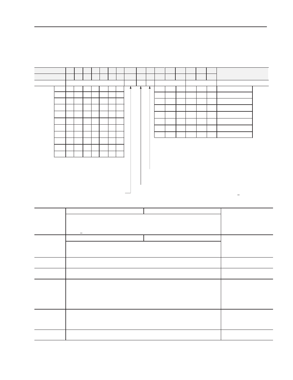
Use the configuration information below to configure your module
to your specifications.For detailed configuration information, see
chapter 5 of your High Resolution Thermocouple/mV Input Module
User Manual (publication 1771-6.5.131).
Dec. Bits
15
14
13
12
11
10
09
08
07
06
05
04
03
02
01
00
De
o
Octal Bits
17
16
15
14
13
12
11
10
07
06
05
04
03
02
01
00
Description
Word 1
Sample time
T
Z
E
Type
Type
Real time sample interval bits - determine the sample
time for updating module inputs. You select sample time in
0.025 second intervals using binary code. (All values
between 0.025 and 3.1 seconds in 0.025 second intervals
are available.) Important: Use decimally addressed bit
locations for PLC-5 processors.
0
0
0
0
0
0
0
1
Zoom enable (Z) - Enables X10 magnification when millivolt inputs have been
selected. Enabling this feature causes the BTR data to display +30.000mV
around the value selected by word 2. Use the digital filter (word 3) to stabilize
the readings when using this mode. 0 = normal 10
mV; 1 = X10 (1mV)
0.1s
0
0
1
0
0
1
0
1
0
0
1
1
0
0
0
0
0
1
0
1
0
0
1
1
0
0
0
0.5s
0
0
1
0.6s
0
0
1
0.7s
0
0
1
0.8s
0
1
0
0.9s
0
1
0
1.0s
0
1
0
1.5s
0
1
1
2.0s
2.5s
3.0s
0
0
0
0
0
0
0
0
0
1
0
0
0
1
1
0
1
0
1
1
1
1
1
0
0
0
1
1
1
0
0
1
0
1
0
0
1
1
1
0
1
1
1
0
1
0
0
Millivolt input
0
0
“B” thermocouple
1
1
“E” thermocouple
0
0
1
“J” thermocouple
0
1
0
“K” thermocouple
0
1
1
“R” thermocouple
1
0
1
“S” thermocouple
1
1
0
“T” thermocouple
1
0
0
(Bits 00-02) Input type codes for inputs 1 thru 8 (or 1 thru 4 if bit
06 is set to 1) - tells the module what type of input device you
connected to the module. See table above.
(Bits 03-05) Input type codes for inputs 5 thru 8 (bit 06 must be
set to 1) - tells the module what type of input device you connected to
inputs 5 thru 8. See table above.
Enable bit for input types (E) - When set to 0 bits 00–02 define input type
for all channels. When set to 1 bits 00–02 defines input type for channels
1–4, and bit 03–05 defines input type for channels 5–8.
Temperature scale bit (T) - when set (1), reports
temperature in
o
F; when reset (0), in
o
C. The module
ignores this bit for millivolt inputs.
Zoom value for group 2 (channels 5-8)
Zoom value for group 1 (channels 1-4)
2
Zoom center value for channels 1–8. These values are used when millivolt inputs have been
selected and bit 07 of word 1 has been set to enable zoom (i.e. 1
µ
V display resolution). Enter a
value in 2’s complement binary format ranging from –70mV to +70mV. The displayed range will
then be +30.000mV around the selected value, displayed in 1
µ
V increments.
Zoom values
Filter value for group 2 (channels 5-8)
Filter value for group 1 (channels 1-4)
3
Filter values for channels 1–8. The filter operates on the display data only. Alarms,
underrange and overrange operate in real time. The filter constant is equal to: TC = 0.025(1 +
filter value).
Filter values
4, 6, 8, 10, 12,
14, 16, 18
Low Alarm Values for channels 1-8
Low channel alarm values
5, 7, 9, 11, 13,
15, 17, 19
High Alarm Values for channels 1-8
High channel alarm values
Low and High channel alarm values that you enter via the terminal in 2’s complementary
binary. Store low and high channel alarms in pairs, low alarm values in even–numbered words,
high alarm values in odd–numbered words. For example, store channel 1 low and high alarm
values in words 4 and 5, respectively. Alarms are disabled by setting the low alarm equal to the
high alarm. If the zoom feature is enabled, the alarm values should be the difference between
the ”actual alarm limit” and ”zoom center value” in word 2.
20, 21, 22, 23,
24, 25, 26, 27
Calibration words are a composite of two independent bytes for each channel. Enter
calibration data in signed magnitude binary only. The most significant bit in each byte is the sign
bit; set for negative, reset for positive. Use the high byte (bits 08–15) for offset correction, the
low byte (bits 00–07) for gain correction for each channel.
Channel 1-8 calibration values
28
Auto-calibration Request Word - Used to automatically calibrate selected channels and save
the calibration constants in EEPROM.
Auto-calibration Request
Word
Configure the Module