Install the module and field wiring arm – Rockwell Automation 1771-IXHR INSTL INSTR HI RES TC/MV INPUT User Manual
Page 4
High Resolution Thermocouple/Millivolt Input Module
4
Publication 1771-5.66 – October 1998
!
ATTENTION: The High Resolution
Thermocouple/Millivolt Input Module uses the same
keying slots as the 1771–IXE Thermocouple/Millivolt
Input Module. If you are replacing a 1771–IXE with a
1771–IXHR, the ladder program must be modified to
accept the new block transfer format.
!
ATTENTION: Remove power from the 1771 I/O
chassis backplane before you install the module.
Failure to remove power from the backplane
could cause:
•
module damage
•
degradation of performance
•
injury or equipment damage due to possible
unexpected operation
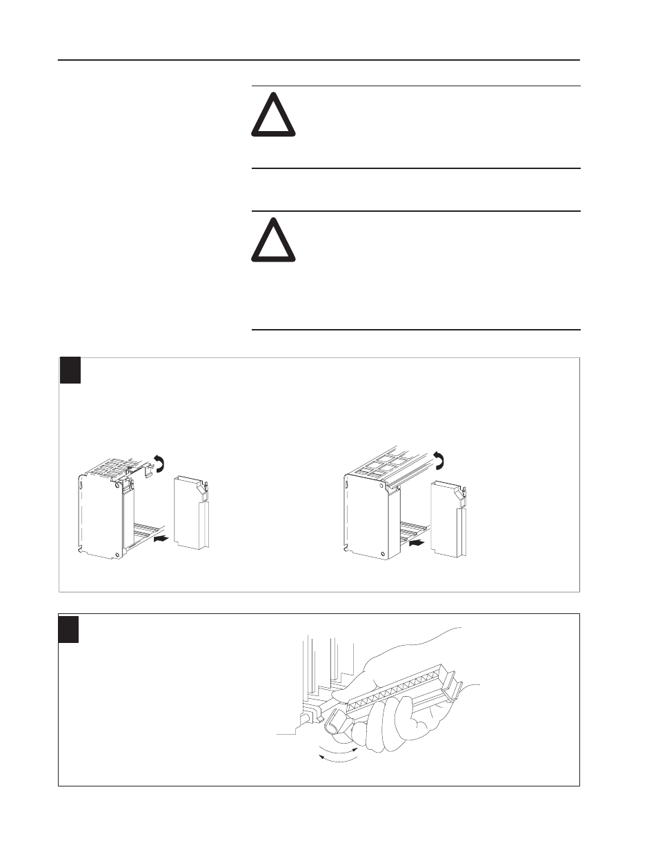
Place the module in the card guides on the top and bottom of the chassis that guide the module into position.
Important:
Apply firm even pressure on the module to seat it into its backplane connector.
1
1771-A1B, -A2B, -A3B, -A4B I/O chassis
Snap the chassis latch over the
top of the module to secure it.
Swing the chassis locking bar
down into place to secure the
modules. Make sure the locking
pins engage.
1771-A1B, -A2B, -A4B Series B I/O chassis
Attach the wiring arm (1771-WI) to the horizontal bar at the
bottom of the I/O chassis.
The wiring arm pivots upward and connects with the
module so you can install or remove the module without
disconnecting the wires.
2
1771-WI
Install the Module and
Field Wiring Arm