Identifying the processor’s front panel components – Rockwell Automation 1785-Lx0E,D178510.5 QUICK START ETHERNET PLC-9 User Manual
Page 8
Publication 1785-10.5 - November 1998
1-2
Overview
Identifying the Processor’s Front
Panel Components
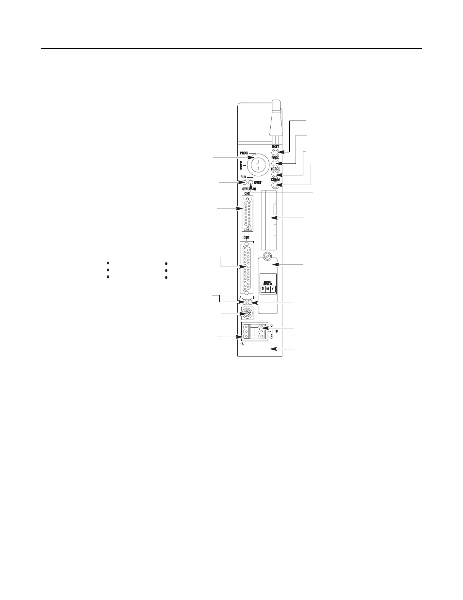
These pictures show the Enhanced PLC-5 processor front panel
components.
PLC-5/20E Processor Front Panel
PLC-5/20E
Programmable
Controller
battery indicator (red when the battery is low)
processor RUN/FAULT indicator (green when
running; red when faulted)
force indicator (amber when I/O forces
are enabled)
channel 0 communication status indicator
(green when the channel is communicating)
Install memory module here
Install battery here
PLC-5 family member designation
channel 1B communication port;
its default configuration is remote I/O scanner
channel 1B status indicator
(lights green and red)
Use this port with ASCII or DF1 full-duplex, half-duplex
master, and half-duplex slave protocols. The port’s
default configuration supports processor programming:
channel 0*25-pin D-shell serial port; supports standard
EIA RS-232C and RS-423 and is RS-422A compatible
one stop-bit
BCC error check
no handshaking
DF1 point-to-point
2400 bps
no parity
keyswitch; selects processor mode
channel 1A communication port; its default
configuration is DH+ communication
8-pin mini-DIN, DH+ programming terminal
connection parallel to channel 1A
channel 2 Ethernet status indicator (green when
functioning normally; red when not functioning)
channel 2 communication port;
a 15-pin Ethernet port
channel 2, Ethernet transmit indicator
(green when the channel is communicating)
channel 1A status indicator
(lights green and red)