Install the plc-5 processor – Rockwell Automation 1785-Lx0E,D178510.5 QUICK START ETHERNET PLC-9 User Manual
Page 15
Publication 1785-10.5 - November 1998
Set up the Hardware
2-5
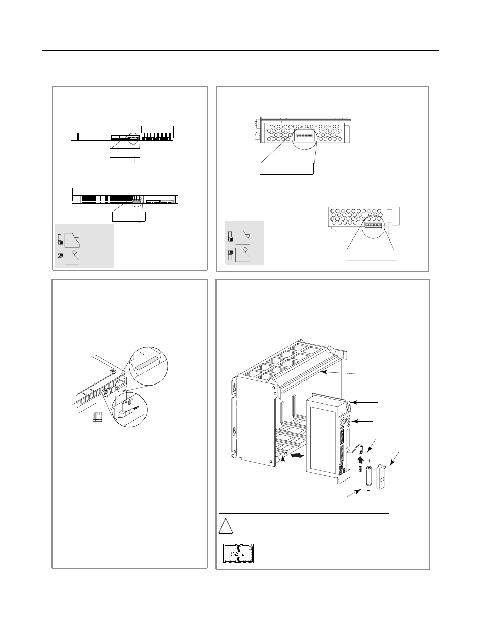
Install the PLC-5 Processor
Define the DH+ Station Address of Channel 1A
by setting switch assembly SW-1.
1
2
Specify the serial communication of channel 0.
Front of
Processor
10
10
Front of
Processor
Bottom view of PLC-5/20E processor switch assembly SW2
Bottom view of PLC-5/40E and -5/80E
processor switch assembly SW2
side view
OFF
Always off
Side View of
PLC-5/20E
processors SW1
Side View of
PLC-5/40E
and
-5/80E
processors SW1
3
ENET
802.3
Hardware
Ethernet
address label
Ethernet
configuration
jumper
Install the processor module.
To install the battery, slide the battery-side connector into the
processor-side connector until you hear them snap together, and
attach the battery cover.
4
5
Identify the Ethernet configuration jumper and
hardware Ethernet address.
IMPORTANT: Do not change the Etherrnet configuration
jumper default setting, which is set at 802.3.
Most Ethernet networks use the 802.3 standard; however
if your Ethernet network is an older network and complies
with the original Ethernet standard, then set the jumper
to ENET.
The hardware Ethernet address label is located to the
right of the Ethernet configuration jumper and shows the
hardware Ethernet address assigned by Allen-Bradley.
For detailed information about handling and disposing
of the battery as well as other important guidelines, see
publication AG-5.4.
ATTENTION: To maintain CSA certification for hazardous
areas, do not substitute any other battery for the 1770-XYC.
!
For series E and later processors:
use this switch to select baud rate
For series D and earlier processors:
this switch is always off
side view
up
230 Kbaud
down
57.6 Kbaud
Locking
Bar
PLC-5/20E
Processor
Card Guides
Lift Eector Tab
20897-M
Battery Connector
Battery
Battery Cover
1 2 3 4 5 6 7
1 2 3 4 5 6 7
1 2 3 4 5 6 7 8 9
1 2 3 4 5 6 7 8 9
More