Gh f-7 – Rockwell Automation 1764-xxxx MICROLOGIX 1500 PROGRAMMABLE CONTROLLERS User Manual
Page 153
Publication 1764-UM001B-EN-P - April 2002
System Loading and Heat Dissipation F-7
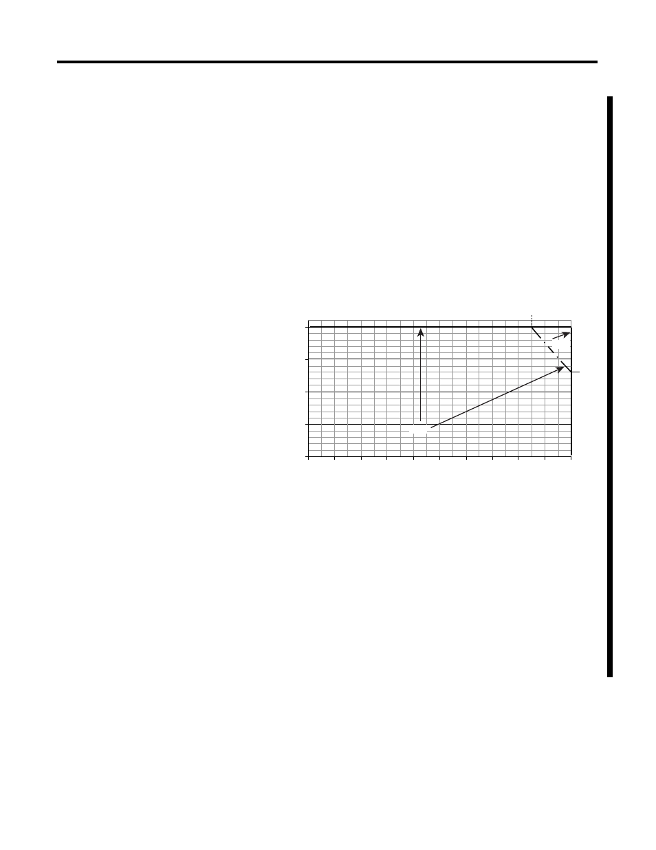
System Using a 1769-PA4
To validate your system, the total 5V dc current and 24V dc current
consumed must be considered. The I/O modules connected to the
PB2 should be distributed, such that the current consumed from the
left and right side of the power supply never exceeds 2A at 5V and
0.8A at 24V dc with an ambient temperature of 0 to 55
°
C. Use the
current graph below to determine if the power supply loading in your
system is:
•
within the allowable range for special load conditions
•
above 55
°
to 60
°
C.
Figure 7 1769-PA4 5V and 24V dc Current
System Using a 1769-PB4
To validate your system, the total 5V dc current and 24V dc current
consumed must be considered. The I/O modules connected to the
PB2 should be distributed, such that the current consumed from the
left and right side of the power supply never exceeds 2A at 5V and
0.8A at 24V dc with an ambient temperature of 0 to 55
°
C. Use the
current graph below to determine if the power supply loading in your
system is:
•
within the allowable range for special load conditions
•
above 55
°
to 60
°
C.
4.0
3.0
2.0
1.0
0.0
0.0
0.2
0.4
0.6
0.8
1.0
1.2
60˚C
1.4
1.6
1.8
2.0
2.6
1.7
55˚C
4.0
3.0
2.0
1.0
0.0
0.0
0.2
0.4
0.6
0.8
1.0
1.2
60˚C
1.4
1.6
1.8
2.0
2.6
1.7
55˚C
+24V Bus Load (Amps)
+5V
B
us
Load
(A
mp
s)
Total Output: 68W at 55°C or below 61W at 60°C or below