Rockwell Automation 1764-xxxx MICROLOGIX 1500 PROGRAMMABLE CONTROLLERS User Manual
Page 145
Publication 1764-UM001B-EN-P - April 2002
Understanding Communication Protocols E-13
Modbus RTU Slave
Communication Protocol
(MicroLogix 1764-LSP and
1764-LRP Series B and later
processors only)
Modbus RTU Slave is a Half-Duplex, master-slave communications
protocol. The Modbus network master initiates and controls all
communications on the network. Modbus protocol allows a single
master to communicate with a maximum of 255 slave devices.
When a MicroLogix 1200 or 1500 Communications port is configured
for Modbus RTU Slave operation, the user must define where Modbus
data (coils, contacts, and registers) is mapped into the MicroLogix data
space.
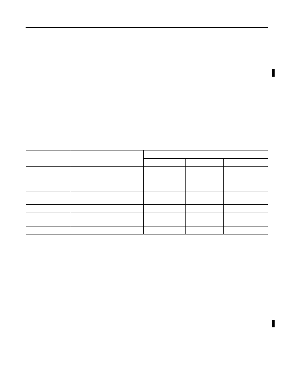
The Modbus address space is comprised of seven distinct memory
ranges. Four of these ranges can be mapped into MicroLogix data
files. Three Modbus ranges are fixed to MicroLogix file 2, the Status
file. The table below illustrates Modbus to MicroLogix mappings.
For more information on the MicroLogix 1500 configuration
parameters for Modbus Slave RTU (Remote Terminal Unit transmission
mode) protocol, refer to the MicroLogix 1200 and 1500 Programmable
Controllers Instruction Set Reference Manual, publication 1762-RM001.
For more information about the Modbus Slave protocol, see the
Modbus Protocol Specifications (available from
http://www.modicon.com/techpubs/).
ASCII Protocol (MicroLogix
1500 1764-LSP and 1764-LRP
Series B and later
Processors only)
ASCII protocol provides connection to other ASCII devices, such as
bar code readers, weigh scales, serial printers, and other intelligent
devices.
You can use ASCII protocol by configuring the RS-232 port, channel 0
for ASCII driver (For the 1764-LRP only, you can select either Channel
0 or Channel 1).
Table E.3 Modbus to MicroLogix Memory Map
Modbus Addressing
Description
Valid MicroLogix Addressing
File Type
Data File Number Address
0001 to 4096
Read/Write Modbus Coil Data space
Bit (B) or Integer (N)
3 to 255
bits 0 to 4095
10001 to 14096
Read-Only Modbus Contact Data space
Bit (B) or Integer (N)
3 to 255
bits 0 to 4095
30001 to 30256
Read-Only Modbus Input Register space Bit (B) or Integer (N)
3 to 255
words 0 to 255
30501 to 30532
Modbus Communication Parameters
Communication
Status Files
2
words 0 to 31
31501 to 31566
Read-Only System Status File space
Status (S)
2
words 32 to 65
40001 to 40256
Read/Write Modbus Holding Register
space
Bit (B) or Integer (N)
3 to 255
words 0 to 255
41501 to 41566
Read/Write System Status File space
Status (S)
2
words 0 to 65